1984 1.9DG to AGG Conversion
Printed From: The Brick-yard
Category: The Brickyard
Forum Name: The Bus Park
Forum Description: Post pickies of yer wagon here. You can post multiple images (Max size 100K each) in a single post. Requires no outside hosting. Be nice and keep it clean please. PHOTOS ONLY.
URL: http://www.brick-yard.co.uk/forum/forum_posts.asp?TID=92151
Printed Date: 20 Apr 24 at 12:34
Software Version: Web Wiz Forums 12.06 - https://www.webwizforums.com
Topic: 1984 1.9DG to AGG Conversion
Posted By: club joker 84
Subject: 1984 1.9DG to AGG Conversion
Date Posted: 31 Oct 16 at 00:10
|
Thought I would share with you the long-running saga of my
AGG engine conversion. Thanks have to go
to GaryD for sharing his ‘bible’.
Certainly wouldn’t have got to this stage without it! I am reasonably mechanically competent and
usually do own servicing etc., but I am no mechanic and this is the most
complicated thing I have attempted. My van is a 1984 Westfalia Club Joker, originally a 1.9DG on
a DU gearbox. About 2 years ago it
started losing water. Held it at bay for
about a year using Wynns Radiator Stop Leak.
I am not usually one for magic potions, but this is impressive
stuff! Worked surprisingly well, but
eventually the water jacket seals were too much for it and I had to take the van
off the road. I had been thinking about
an AGG conversion for a while, and this seemed like the time to do it. I had previously stockpiled most of the JX bits needed for
the conversion: -
Sump -
Mounts -
Engine bars (including the plates welded into
the van). I think mine are the early bars -
Bell housing -
Exhaust back box -
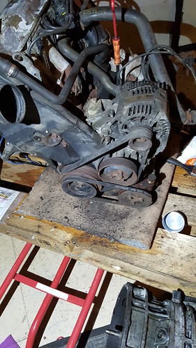
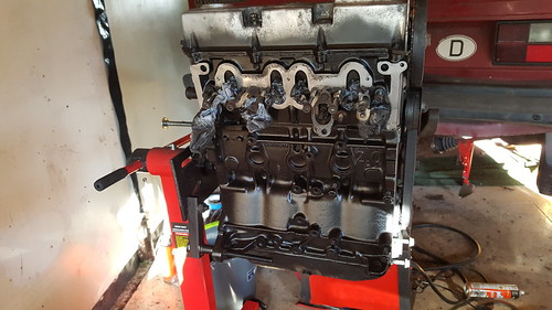
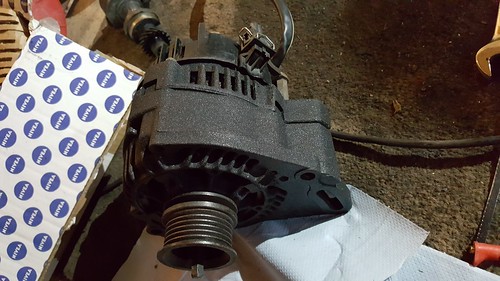
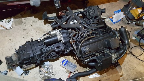
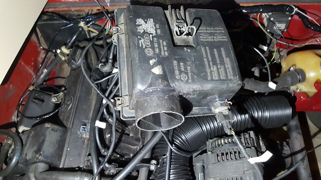
Oil pump, dipstick, filler neck Took a chance and managed to get and AGG engine + loom + ecu
+ immobiliser + MAF, etc. from ebay for £100. Was a non-aircon model, which was result as it
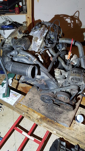
has the right alternator and stand from the start. This is what it looked like on arrival – bit grubby,
but no signs of any leaks etc.:
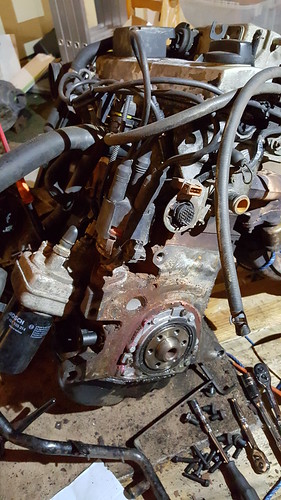
Dropped the original engine and gearbox out of the van and
onto a pallet using a couple of jacks. Lifted
the van as high as I could get it on axle stands and dragged engine and box out
from underneath. Split the box from the
engine
Brought a cheapie engine stand off e-bay (£34
delivered!). Using a jack and a great
deal of swearing, I managed to fix the GTI engine to it after taking off the Golf
clutch and flywheel. (Top tip – if you
have an engine on a pallet balanced on to of a trolley jack and partly bolted
to your engine stand, make sure that the other bolts you need are within
reach!). Took all of the ancillaries off the GTI engine, labelling as
I went and putting them in boxes.
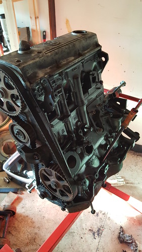
Cleaned it up using Gunk, hot water and small brushes, followed by the
cheap soap filled scouring pads you get in the supermarket and finally with
thinners. Any really grubby bits got a
going over with a wire brush on a cheapie drill from screwfix. Wanted it to look nice, so painted it with
high temp paint - Plasti-Kote Black Satin BBQ Paint. Seems like good stuff. Stays a bit soft until it’s got hot, but
looks really good. Time will tell how it
stands up to oil, etc.
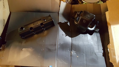
Any bits that were
small enough got the same treatment, and were then put in the dildo oven at
full temperature (waited until my wife went out!). This included the manifolds, sump, etc.
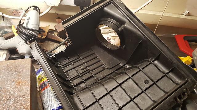
Mounts, etc. got the same again, but Halfords Truck Bed liner. Again, time will tell how it lasts. Before painting, the mounts were cleaned with
a wire brush and drill. They had quite a
lot of surface rust, so took a chance on cleaning them up using citric
acid. Got a 5kg bag of it from e-bay.
Mixed it up with hot water in a storage box and soaked them overnight. The results were really impressive, so
everything else that was rusty got dipped and sprayed from then on! Didn’t take any pictures of this for some
reason, but it was good. Went for a coat
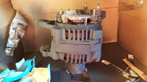
of etch primer (UPOL) before the truck bed liner. Alternator was also cleaned and painted. Took the obvious bits off first, but didn’t
go mad. Slipped bits of cardboard into the
cooling bits to mask off the copper windings.
Came out nice.
You may have noticed that I managed to get an allen key
stuck in my alternator pulley bolt. It’s
still there. I can’t get it out, no
matter what I try. I think I’ll just
live with it! I was getting a bit anal about the whole thing now, so splashed
out in stainless bolts. I went for http://www.liquidmetalrefinement.co.uk/store/p7/Vw_Golf_Mk2_GTI_8V_Stainless_Steel_Engine_bay_bolt_nut_washer_kit_over_80pcs..html" rel="nofollow - these
ones from Liquid Metal Refinement.
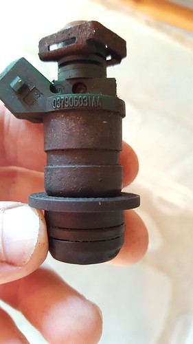
Not an exact match for the AGG, but not far off. Came clearly labelled etc. so was happy with
them. Injectors looked a bit manky:
Decided to rebuild them.
Used http://mrinjectoruk.co.uk/Fuel-injector-service-kit-bosch-0280155-fiat-peugeot-vw-our-seal-kit-2-P246098.aspx" rel="nofollow - this
kit from Mr Injector UK. Quite easy
to do. Used plenty of injector cleaner. Got new water pump, cambelt, oil filter, plugs, leads, rotor
arm, dizzy cap, thermostat, gaskets, etc. from GSF. Also picked up a second hand starter and JX
header tank bracket. From Brickwerks I
got clutch pilot bearing, thermostat housing, flywheel bolts, fuel pump and
filter, a 2.1 fuel supply hose kit and bulkhead pipe fitting, bell housing bolts
and silicon JX cooling hoses. Built the engine
up on the stand as per GaryD’s instructions.
I did manage to retain the heat shield around the exhaust manifold by
cutting bits away with tin snips until it fitted. I had to fabricate a little bracket to hold the dipstick in the
right place. Used the old clutch slave
bracket support. This bolted up to the lifting eye.
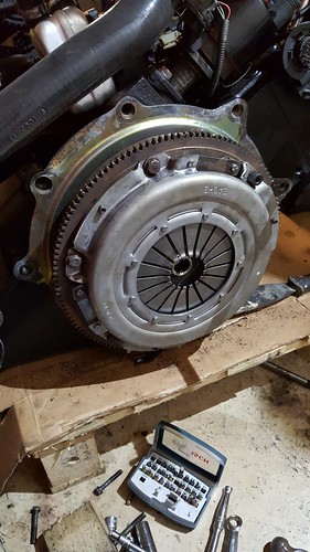
Put engine back on pallet (more swearing) and fitted clutch
and flywheel.
|
Replies:
Posted By: club joker 84
Date Posted: 31 Oct 16 at 00:13
|
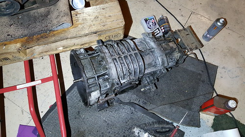
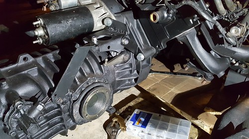
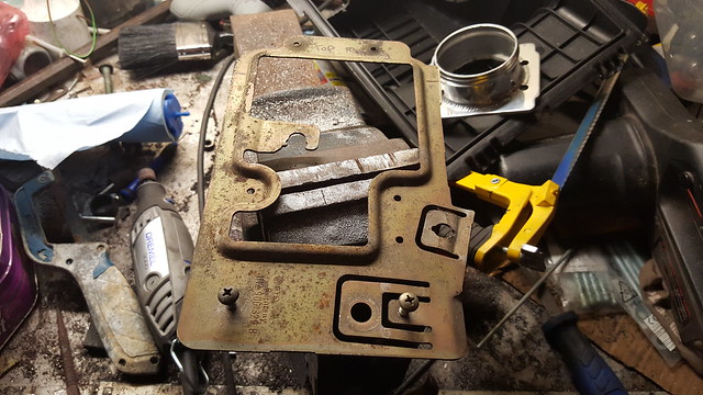
Time to sort out gearbox. Gave it a good clean up using allow wheel cleaner, scouring
pads and wire brush. Took bloody
ages. Drained oil and stood it up on its
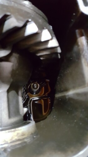
end and removed the bell housing. After
a lot of head scratching I managed to remove the input shaft. There is a sleeve that fits over the end
facing into the gearbox. This has
splines that stop it unscrewing. You
just lift this up and out of the way (easier said than done!) and unscrew. You can just about see the place where it
screws into in this picture.
I didn’t have a diesel one to swap it for, so I carefully
cut it down using a hacksaw and filed a chamfer on it. That stuff is seriously hard! Refitted it and diesel bell housing with new gasket and
bolts. It all then had another clean up
and a spray with etch primer and truck be liner. It was at this stage that I noticed that the
clutch cross shaft was quite loose in the bellhousing. Also,
the splines on the end the circlip groove were quite knackered, so I decided to
swap it for the one from the petrol bell housing.
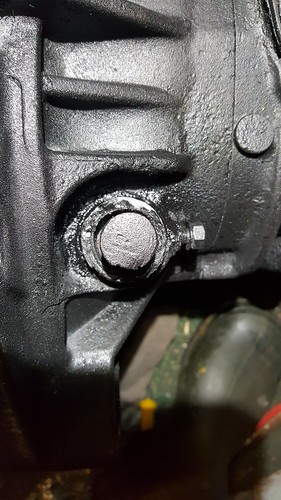
Had to cut the clutch arm off both of them in the end! It looks like the diesel clutch slave bracket
had sheared off its mount to the starter bolt and been slopping around for a
while and worn away this area of the bellhousing. Wasn’t about to splash out on another bell
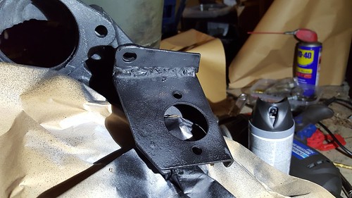
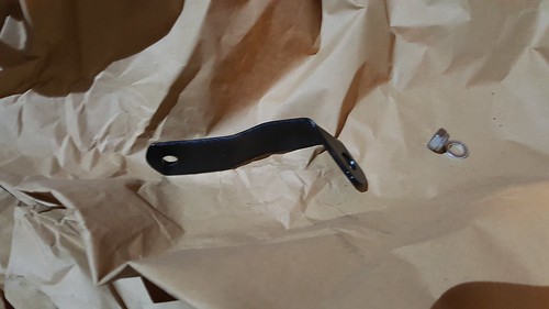
housing, so decided to beef up the way that the clutch bracket mounts. First I welded an additional plate onto it to
repair the mount to the starter bolt.
Then I bent up another bracket that would mount to another
of the engine bolts.
I also filled in the worn bit of bell housing with chemical
metal and assembled it all, with new bushes.
All seems very solid, so happy with it.
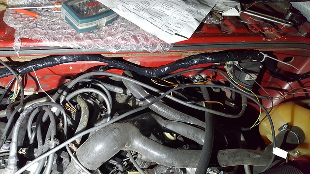
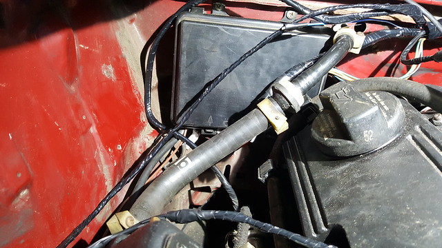
Then it was all bolted up to the engine with starter etc,
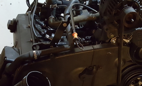
and new hoses. These were a bit of a
head scratcher as I didn’t have any references.
After plenty of Google image searching I worked it out. The main tricky bits to work out were the
link between the water pump, the flange on the head and the oil cooler. In the Golf they are all linked with one
hose. In the T3, the oil pump isn’t
connected to this hose, but to one of the main hoses. I used the original Golf hose and put a bung
in the hole that used to connect to the oil cooler. Another one is where the extra, electric
coolant pump usually goes. This is
apparently not needed for the AGG, so you just join these two bits
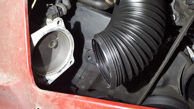
together. Lastly, the two water pipes
from the throttle body. I connected on
to the manifold on the side of the head (kept the Golf one and there was an
inlet of the right size on it). Just
blocked the other one up. Not sure if this
is right or wrong. Hopefully you can see
them in this picture.
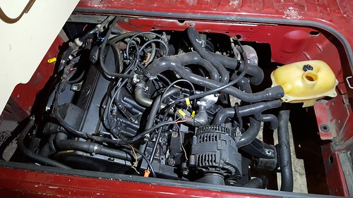
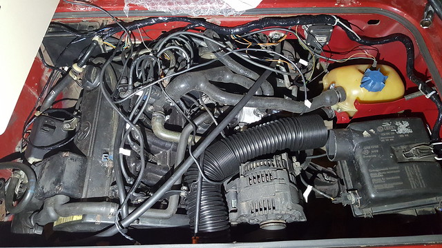
Got it mounted in the van using my patented pallet, jack and
swearing method.
Set to on the wiring, followed GaryD’s notes on this. Daunting as it seems at first, it is quite
straightforward and you cut out most of it.
Just follow everything from the ECU connector and keep it. Remove everything else I think. Plugged it all in.
Added a multicore cable to the front for speed sensor, immobiliser, etc. Mounted immobiliser and OBD socket behind
dash. Fired it up, but it wouldn’t run
for more than a few seconds. Had an
immobiliser-related error code, so cleared that. Moved a few earths around and tried
again. It held on a bit longer. Had an error code relating to the hall
sender, so reset distributor timing and it runs! Anyway, that’s where I am up to with it. Thought I would share whilst I finish it
off. Don’t expect quick progress, I grab
a few hours when I can! |
Posted By: Bromy
Date Posted: 31 Oct 16 at 00:42
Nice one, looking good  ------------- "follow the masses, do the opposite" |
Posted By: fufflenarnia
Date Posted: 31 Oct 16 at 18:18
| Good work, it's a cracking conversion |
Posted By: club joker 84
Date Posted: 16 Nov 16 at 22:37
|
Bit if an update.
Managed to get a few hours on the van the other day. As mine started life as petrol, my battery is under the
passenger seat, leaving me with a big space in the back right hand corner of
the engine bay. The plan is to mount the
ecu behind the offside rear light, with the airbox in front of it. First job was to flatten out the ECU mount so that I can
bolt it all up easily. Just did this in
a vice. Will get some plastic bolts and
stick on feet so that I can mount this and keep it insulated from the chassis.
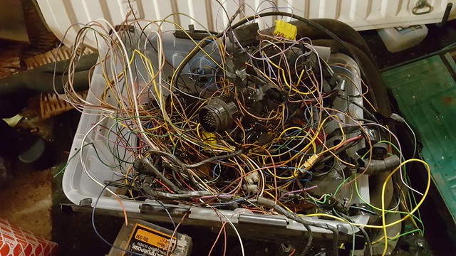
Next job was to shorten the loom so that it fitted well
around the front of the engine bay. This
was pretty tedious, and involved cutting about 14 inches out of each wire,
stripping the ends back and soldering them together. Each one was then covered with
heatshrink. I tried to stagger the cut
points so that I wouldn’t end up with a bulge where all the joins were. By the time you have done about 35 of these
it gets quite boring! No pictures of
this bit. Here's a picture of all the crap that was cut out from the whole loom: https://flic.kr/p/Peiyif" rel="nofollow"> Next job was to wrap the loom. I used non http://www.12voltplanet.co.uk/pvc-harness-tape-non-adhesive-19mm-x-40m.html" rel="nofollow - adhesive loom tape for this. I used black insulation tape to tape the loom up every 4 inches or so, with extra tape around any branches to prevent it being pulled out of shape. I then wrapped it all up in the loom tape. This was easy to do, but quite time consuming.
Also managed to get all of the relays, fuses, etc. tucked away in the original wiring box in the engine bay. It is absolutely packed in there, but the lid does just about go on. https://flic.kr/p/PeiJcd" rel="nofollow"> The plan is to
fix the loom in place using cable ties and mounting blocks – a job for another
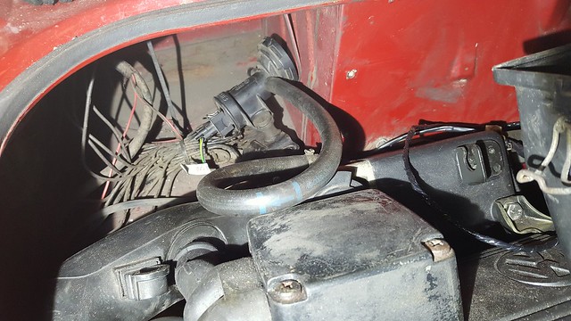
day. https://flic.kr/p/PeiJqQ" rel="nofollow"> Charcoal canister valve thing will go behind the nearside
light, nice and close to the throttle body, so that the hose can be connected
up as per the GTI. Don’t think this is
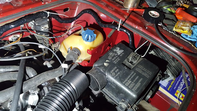
really necessary tbh. Loosely in place here: https://flic.kr/p/P4ZokW" rel="nofollow"> The other job I tackled was the airbox. I wanted to try to use a full airbox if
possible just to keep it a bit quieter and more factory looking. I had the original square DG box, and the GTI
one. The GTI one is a fair bit bigger
and has a larger outlet and also a fixture for the inlet temperature sensor. The intake to the box seems to be smaller if
anything. I couldn’t find a good way of tucking the GTI box under the
engine lid, so I started to think how I could use the DG box. The smaller outlet and lack of a sensor mount
were a problem. I had the original mount
that I had removed to make way for the coolant tank. After a bit of measuring out and a couple of
trial runs, I found that I could weld it to the chassis rail, allowing the
airbox to be mounted. https://flic.kr/p/P4ZQ99" rel="nofollow"> I needed to find a way of clipping it in place. The original clip just attaches to a loop of
stiff wire. I couldn’t see a way to get
this out to reuse it unfortunately.
However, I think it would have been too short, as the airbox is lower
than it was originally. I looked around my
workshop for something I could use. I found a bucket with a strong wire handle,
so cut it off. I made up a dummy one
from some soft garden wire, and then bent the bucket handle to match. Fortunately there is already a hole in the
bottom of the engine bay cross member just in the right place, so I used this
to mount the wire. I just bent the ends
at right angles, cut them quite short and put them up through the hole. The spring tension of the wire holds it in
place. https://flic.kr/p/Pht1n2" rel="nofollow"> The box clips in place really nicely, so I was pleased with
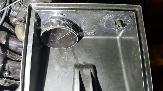
that https://flic.kr/p/P4T5qj" rel="nofollow"> The outlet from the GTI box is a separate piece that kind of
screws into the main box. It’s got a lip
on it, so I thought it might be possible to cut out the original DG outlet,
enlarge the hole and put the GTI outlet through from the back and glue it in
place. A bit of careful marking and
using a dremel soon had the hole big enough.
I just took it slow and kept trying it for size. I did the same thing for the inlet temperature sensor mount. I cut it out of the GTI box, with a section of box around the mount. https://flic.kr/p/PeivJs" rel="nofollow"> Cut a new hole in the DG box and put the GTI sensor mount through from the back. These were then fixed in place using black silicon sealant / panel adhesive stuff.
Came out quite neat in the end: https://flic.kr/p/PeiF1y" rel="nofollow"> I have a length of Flexi Duct http://www.autosiliconehoses.com/silicone-hose-shop/air-ductings/pvc-plastic-air-ducting.html" rel="nofollow - http://www.autosiliconehoses.com/silicone-hose-shop/air-ductings/pvc-plastic-air-ducting.html . Plan is to run this around the back of the alternator,
under the dipstick and onto the MAF.
Loosely in place in this picture. https://flic.kr/p/PeiAoh" rel="nofollow"> 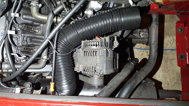 I plan to make up a bracket to hold the MAF in place using the blind bolt hole from the front of the GTI engine (not sure what this is supposed to be for). This will be one of the next jobs… https://flic.kr/p/PeiGah" rel="nofollow"> More to follow when I get a bit more time on it. |
Posted By: rowlesy
Date Posted: 17 Nov 16 at 21:09
|
looking good and some nice solutions for the airbox ------------- UberFukz broke another! sucky sucky five dollah! always out numbered never out gunned! RWS welding 07846 380 467 (worcs) |
Posted By: booted
Date Posted: 23 Nov 16 at 11:04
|
My dg airbox is nothing like your one is there a part number on it ? http://smg.photobucket.com/user/booted/media/4sale/2012-04-28144729.jpg.html" rel="nofollow"> 
|
Posted By: Bromy
Date Posted: 23 Nov 16 at 13:18
|
His is from the donor isnt it? ------------- "follow the masses, do the opposite" |
Posted By: booted
Date Posted: 23 Nov 16 at 13:50
| I thought you cut up the donor one and fitted the bits to tha square one in the photo |
Posted By: Bromy
Date Posted: 23 Nov 16 at 17:10
Yeah i think your right actually  ------------- "follow the masses, do the opposite" |
Posted By: club joker 84
Date Posted: 23 Nov 16 at 22:53
|
My original DG airbox is / was square, like this one: https://flic.kr/p/Pxj7CB" rel="nofollow"> 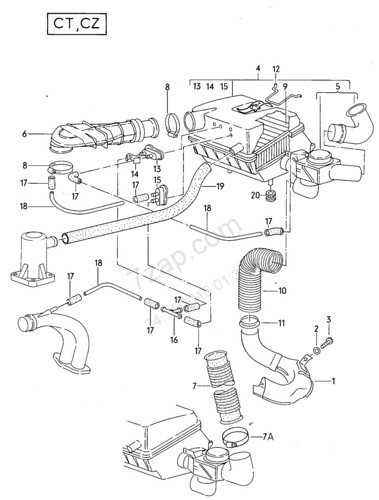 I think that this is the early version. If you click on my photos of it you should see a huge version where you can see the part numbers. I grafted the Golf outlet and air temp sensor into this. The Golf box is also square-ish. Not sure if you would be able to do this with the round version. http://retrorides.proboards.com/thread/35344/1988-vw-type-25-exhaust?page=8" rel="nofollow - This guy has found a nice neat way to use the Golf box though.
|
Posted By: Titus A Duxass
Date Posted: 24 Nov 16 at 16:11
That's very similar set up that I've done using a Hyundai Getz air box. ------------- Bollocks to it all!! 51°24′N 12°52′E |
 club joker 84 wrote:
Posted By: club joker 84
Date Posted: 07 Dec 16 at 23:21
|
More progress on the air intake. Firstly I had to modify the airbox I had made a bit because the hose that I had bought didn't quite fit over the outlet. I had to slot in something just a bit smaller. After rooting through bits and bobs in my workshop, I found just the right thing. Of all things it was one of those small cans of baked beans! To get it in there, I cut the outlet short, user a Dremel to cut down the air guides inside a bit and slotted it in and used the same mastic stuff to glue it in place. Once it was all dried I gave it a blow over with etch primer and matt black paint. https://flic.kr/p/PKXRZw" rel="nofollow"> 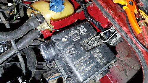 Next step was to make up a bracket for the MAF. This was done from a little strip of steel that I had hanging around. I made a card template first and then copied it. Nothing complicated, just bent using a vice and cut and filed to shape. https://flic.kr/p/PPbndP" rel="nofollow">  https://flic.kr/p/NyzMQf" rel="nofollow"> 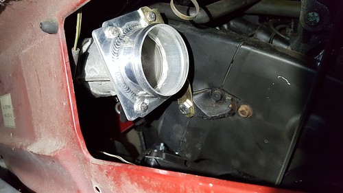 The bracket just bolts up to the MAF adapter and to the blind tapped hole on the front of the engine block. Then I got the air hose on: https://flic.kr/p/PfxMio" rel="nofollow"> 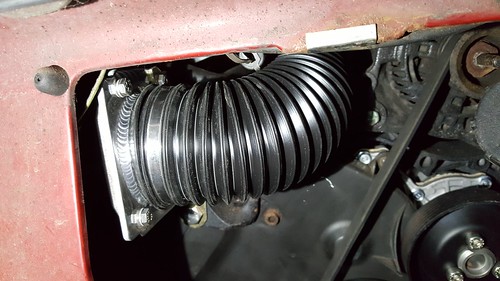 https://flic.kr/p/NzQ4Rt" rel="nofollow"> 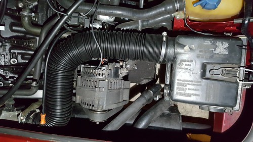 Also got the ECU mounted. This went behind the right rear light. I use the original mounting plate, but drilled some extra holes and used plastic nuts and bolts to isolate it from the body. https://flic.kr/p/NyzRj9" rel="nofollow"> 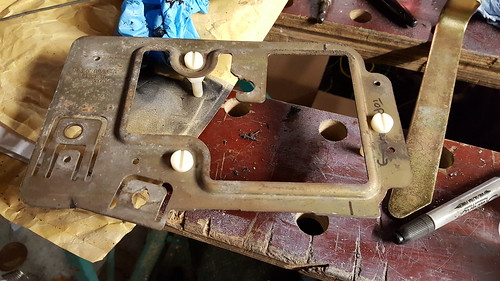 https://flic.kr/p/NyzQDm" rel="nofollow"> 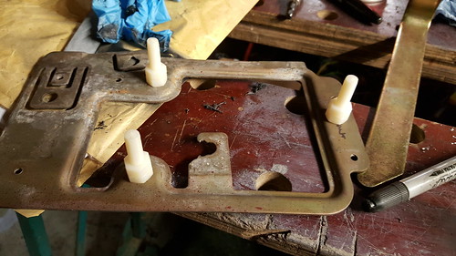 https://flic.kr/p/NzQ61T" rel="nofollow"> 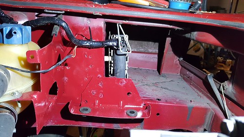 https://flic.kr/p/PArHrQ" rel="nofollow"> 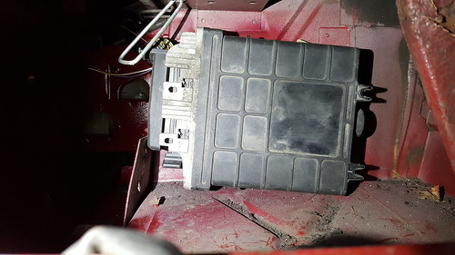 Next step, exhaust. I have used an old wire coathanger to bend to shape and measure, and ordered some bits and pieces from http://profusionexhausts.com/" rel="nofollow - Profusion Exhausts . I hope I can use theseto fabricate something similar. I have the original diesel silencer, so the plan is to make up a piece to join it to the exhaust manifold. Plan is to add an extra silencer too. I will try to copy the merge length from the original manifold to keep the torque. This will be 304 stainless. If anyone's interested I can post up the list of bits I ordered, was about £140 I think. I have also bought a 304 stainless flange from a http://forum.club8090.co.uk/viewtopic.php?f=17&t=156761" rel="nofollow - guy on Club 80-90 who has had some cut. Exciting parcel arrived this afternoon - https://flic.kr/p/NGEYZS" rel="nofollow"> 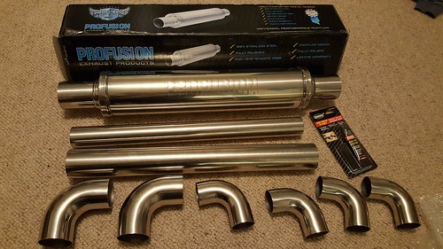 Any tips for welding stainless? Not done it before. Got a fairly basic hobby mig, so will be using disposable bottle gas. I think I need 309 grade wire (might be 308, need to check).
|
Posted By: rowlesy
Date Posted: 08 Dec 16 at 17:31
|
Just the wire will do chap and slow your wire speed down to get the heat in - don't be tempted to cool anything down quickly to get the job done you'll get cracks either sides of the welds ------------- UberFukz broke another! sucky sucky five dollah! always out numbered never out gunned! RWS welding 07846 380 467 (worcs) |
Posted By: Forden341
Date Posted: 08 Dec 16 at 19:13
|
I'd be interested in knowing what your plans are with the exhaust and seeing how it develops. I have an 16v ABF in my crewcab running a temporary exhaust set up using a JX silencer. It's been like that for 6yrs now!! You bought the stainless flange from me so I'm just about to do something similar. All the best. Bert. |
Posted By: rowlesy
Date Posted: 09 Dec 16 at 06:38
Can't rush perfection! ------------- UberFukz broke another! sucky sucky five dollah! always out numbered never out gunned! RWS welding 07846 380 467 (worcs) |
Posted By: club joker 84
Date Posted: 21 Jan 17 at 22:53
|
Too right, no point in rushing! I have done a bit more though... First stop was a speed sensor. I know that these are available from Brickwerks, RJES and Speedpuls in Germany, but I thought that i might be able to make one. Had a dig around on the net and found http://subaruvanagon.com/tom/Speed%20sensor.htm" rel="nofollow - this website where a guy in America has made one using a Hall effect sensor, a zener diode and 2 resistors, probably less than £5. He is putting it in a Subaru conversion, and the ECU only wants a 5V signal from the speed sensor. I believe that the AGG ECU wants 12V. What I have done is to swap the 5V Zener diode for a 12V one. I am no expert, but I think that this will do the trick. I have tried to add in an LED just to make diagnostics a bit easier. I made the circuit from the website up on a small piece of prototyping board which I had filed to shape to fit in place in the speedo as per the factory sensor. Here's a few pics... Testing the circuit to see if it works. 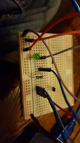 Circuit in place on rear of speedo. [ 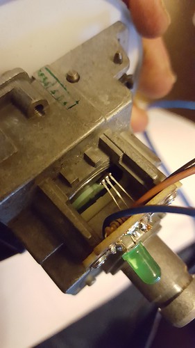 Note that hall sensor has to be bent to shape and located pretty close to the rear of the speedo to pick up the magnet that is already on it. 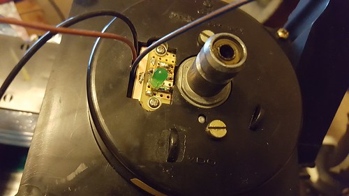 Here's a view of it all in place and bolted back together again. Not as neat as the professional ones, but a fair bit cheaper. Definitely gives a signal output when I have run the speedo with my drill. LED doesn't work, but I went for quite large resistors. As long as the signals works I am not too worried. Not tried connecting it all up to the van yet, but it seems to work on the bench. Time will tell...
|
Posted By: club joker 84
Date Posted: 21 Jan 17 at 23:28
|
i have also made a start on the exhaust. I have a stock na diesel backbox, so really just need to connect this to the AGG exhaust manifold. I bought the following from Profusion Exhaust (all in 1.5mm wall thickness): 2 x 2.25" 57mm 90 degree Tight 1D Mandrel Exhaust Bend T304 Stainless Steel Polished 2 x 1.75" 45mm 90 degree Tight 1D Mandrel Exhaust Bend T304 Stainless Steel Polished 1 x 1.75 inch X 500mm 304 stainless steel exhaust pipe 1.5mm Wall Tube 1 x 2.25 inch 4 x 4 Round 18 inch Polished Stainless Steel Profusion Universal Exhaust Silencer 304 Stainless Steel Exhaust Lambda boss Nut Weld-on M18 x 1.5 O2 Oxygen sensor 2.25" inch 57mm Stainless Steel Joint Clamp heavy duty exhaust band Hi-Temp 1100°c Exhaust Assembly Paste Sealer Repair putty Hole Crack joint kit I did also have the stainless flange as well, but I made a complete balls of welding it and warped it. Doh! As well as the above, I got a reel of 309 stainless welding wire and a cylinder of gas. Because I warped the stainless flange I had, I went with the original flange and just hacksawed the old flexible mounts off it. The old exhaust just pulled off. This left two stubs approx1" long. The 1.75" tube was a good fit over these, so I just slipped it over and welded it in place. I just kept chopping and cutting and trying it in place and tacking it together. I tried to tried to keep the primary pipes reasonably long, as I understand this gives better low down torque, they are probably a bit longer than stock. The 16" silencer is a pretty tight fit. I cut down the flanges on the end to shorten it. It just about fits, but a 14" would probably be better. The only other significant change was that I cut the flange off the original van exhaust. This means that the new exhaust can just clamp over it. Pictures tell the story really. Hoping to finish this off tomorrow, as it is only tacked in place at the moment. https://flic.kr/p/RcPG9Y" rel="nofollow"> 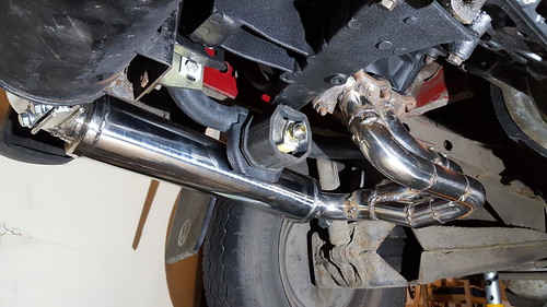 https://flic.kr/p/QRM593" rel="nofollow"> 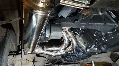 https://flic.kr/p/Qcstq2" rel="nofollow"> 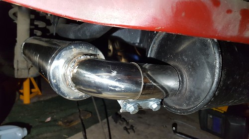 https://flic.kr/p/Q9EkHU" rel="nofollow"> 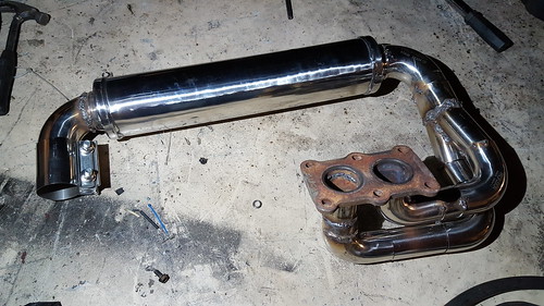 https://flic.kr/p/QRM2AY" rel="nofollow"> 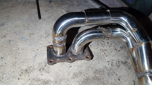 https://flic.kr/p/RcPDqw" rel="nofollow"> 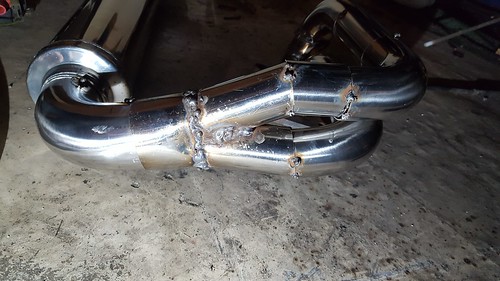 Impressed so far with the quality of the parts from Profusion. Nice and thick and really well made.
|
Posted By: fufflenarnia
Date Posted: 21 Jan 17 at 23:32
|
Good work
|
Posted By: club joker 84
Date Posted: 22 Jan 17 at 22:35
|
Thanks mate - feels like I am making progress! Finished the exhaust off today. Welded it all up and fitted it all up. Nice and quiet now  . Doesn't seem to leak anywhere. I also dropped the standard exhaust down a bit because it barely had any clearance from the rear valance. Here are a few pictures: . Doesn't seem to leak anywhere. I also dropped the standard exhaust down a bit because it barely had any clearance from the rear valance. Here are a few pictures:All welded up - https://flic.kr/p/ReK6h9" rel="nofollow"> 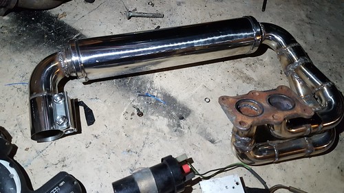 Fitted - https://flic.kr/p/Rpz4aC" rel="nofollow"> 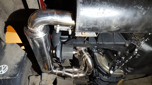 Pretty happy overall. Job left to do: - refit clocks and connect speed sensor - fit fuel pump and filter mounts - T eberspacher (sp?) into fuel return line - tidy up fuel pipes in engine bay - fit gear linkage - fit new CV joints (old ones are knackered!) - put front seats back in - MOT - take kids camping in newly working van - fit sub under passenger seat (non essential!) - got an idea to put together and http://ecomodder.com/wiki/index.php/MPGuino." rel="nofollow - MPGuino. (again, non essential!) Immobiliser seems to be quite choosy. Golf key needs to be taped right over the key reader coil before it will start, Bit annoying, because I have cut away part of the steering column so that it fits around the ignition barrel, but it won't work in this position.
 Would like to have it so that i can combine my van key with the golf key. Any ideas anyone? Do the coil readers tend to become less sensitive over time? Would like to have it so that i can combine my van key with the golf key. Any ideas anyone? Do the coil readers tend to become less sensitive over time? |
Posted By: Bromy
Date Posted: 22 Jan 17 at 23:39
|
Looking good How impressed are you with the silencer? Dampen the noise nicely? ------------- "follow the masses, do the opposite" |
Posted By: fufflenarnia
Date Posted: 23 Jan 17 at 20:01
|
For the key, I had a right click unit which uses a vw look alike flip key it has a space for the chip, but isn't as strong as a vw key and snapped after use. I had to cut down and profile a standard key to fit. You may be better opening the golf key and seeing if you can graft your key into the key top. |
Posted By: fufflenarnia
Date Posted: 23 Jan 17 at 20:04
| The coil will be weaker if the voltage is low, may be worth checking. |
Posted By: club joker 84
Date Posted: 23 Jan 17 at 22:25
|
Hi guys, Yes I am happy with the silencer. It is certainly well made and nice and solid. As for noise, I don't really know for sure, as I have only had it running with the open manifold before. It is definitely a lot quieter than that! I am also running it inside, so it still sounds quite loud, but then so does running any car in a workshop. I will see if I can sort out a video and you can judge for yourself. Thanks for the pointer on the coil. Van has been sitting for a long time, so battery may be down a bit. I have had it on trickle charge though. Will double check what it's getting. I had similar trouble when I first went to start it and tried doing it with the charger connected, so it should have been seeing 12v. Still would not work 'properly' and only with the key right in the centre of it. The immobiliser is connected straight down to the fuse box, but maybe it is not a great earth. Will have a dig around and see what's happening. |
Posted By: club joker 84
Date Posted: 25 Jan 17 at 14:27
|
Not done a video as yet on the noise side of things, but have done some science (ish). Downloaded a sound meter app on my phone. Not saying that the readings are accurate, but do give a reasonable comparison. Readings taken close to tailpipe. First up - our other car 2004 Nissan Cube. 1.4 petrol. This is a very quiet car. It is front engined, rear exhaust, so reading is pretty much exhaust only. It is possible to have a normal conversation standing close the exhaust with the car idling. Reading taken outside. https://flic.kr/p/RmL6VZ" rel="nofollow"> 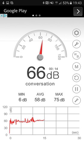 Next up - the van with new exhaust in place. Obviously rear engined, so inevitably engine noise in the reading as well. Engine cover hatch is still off, but boot was closed. Van on axle stands. Reading taken in workshop, but with double doors open. https://flic.kr/p/RxyGJt" rel="nofollow"> 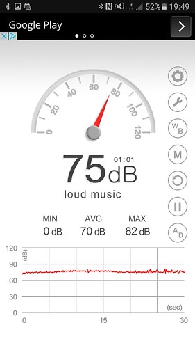 Not a huge amount more decibels, but they are logarithmic reading, so the gaps get bigger between them. Real world, you have to raise your voice to have a conversation next to the van. Not shout, but speak pretty loudly. I expect the noise to come down a bit with the hatch in place. Overall I am happy with it. Definitely quieter than the old WBX. On the voltage thing, I still need to get my multimeter out. Re-connected the Eberspacher last night. Have connected it up to the fuel return line to avoid any conflicts with the new electric fuel pump for the engine. Heater all pumps fine and fuel is getting through, but won't fire. I think that they are also quite sensitive to voltage, so quite possible that the battery is a bit low. Will get it on charge and see what happens.
|
Posted By: Bromy
Date Posted: 25 Jan 17 at 17:22
|
Thanks for taking the time, i think ill look into the same silencer for mine ------------- "follow the masses, do the opposite" |
Posted By: fufflenarnia
Date Posted: 25 Jan 17 at 17:44
| The diesel silencers can lack wadding, so you may find a good quality 2.1 injection silencer is even quieter. |
Posted By: fufflenarnia
Date Posted: 19 Feb 17 at 21:59
| Hi, have you had chance to test your vss yet? I'm hoping it works as I may borrow that idea! |
Posted By: club joker 84
Date Posted: 20 Feb 17 at 22:36
|
Err,sort of! It didn't work Started engine and span speedo up with a drill whilst data logging in vcds. The speed stayed at 0mph. Have built another one to a different circuit design. This new design worked fine with a magnet operating the hall sender. Not sure if the magnet in the speedo will be man enough to activate it. Will try and have a go with it (i.e. Wire it up and spin the speedo up with my drill) later this week. Done a few more unexciting jobs like reconnecting the gear linkage and bodging up an accelerator cable. Will do a bit of an update at some stage. |
Posted By: club joker 84
Date Posted: 22 Feb 17 at 00:21
|
Help! Clutch problems! Put the driveshaft back on the nearside of the van tonight. What a pain in the arse of a job. Anyway, one side done. I decided to call it a night and relax newly aching shoulders. Thought I would give it a gentle go just to see if I could get all the gears OK. Engine on, and clutch dipped. Then slipped it into first, slowly let clutch up, but nothing happened. No biting point, nothing. Same story in all of the gears - gutted! Had a poke around under the van. Slave cylinder seems to work ok (ie move in and out) bracket isn't flexing or anything. It is still the petrol slave cylinder, and but diesel release arm. Are they incompatible? What have I done wrong!? All suggestions and ideas gratefully received! |
Posted By: T3 Nev
Date Posted: 22 Feb 17 at 09:08
| Fit both driveshafts first. |
Posted By: rowlesy
Date Posted: 22 Feb 17 at 20:06
yes your differential is releasing the energy through the lest resistance - the other side of the gearbox with no drive shaft! ------------- UberFukz broke another! sucky sucky five dollah! always out numbered never out gunned! RWS welding 07846 380 467 (worcs) |
Posted By: Bromy
Date Posted: 22 Feb 17 at 21:28
|
I had to result to dropping one tyre on the deck whilst i checked all mine by hand, whilst it wasnt running like ------------- "follow the masses, do the opposite" |
Posted By: club joker 84
Date Posted: 23 Feb 17 at 00:03
|
Thanks guys. Fitted other drive shaft tonight and all is well I think. Wheels definitely spin around now which is good news. I definitely need to sort out my gear shift though - it's all over the shop! More good news is that my diy speed sensor actually works! Checked with the data logger in vcds and I can change the speed by spinning the speedo over by hand. Will post full details, and circuit later this week. Nearly there now! |
Posted By: fufflenarnia
Date Posted: 23 Feb 17 at 06:49
| Excellent, can you put up a wiring diagram so I can plajorise it 😀 |
Posted By: club joker 84
Date Posted: 24 Feb 17 at 01:19
|
OK - speed sensor circuit! First, proof that it works (click that for a video): https://flic.kr/p/SbWDcZ" rel="nofollow"> 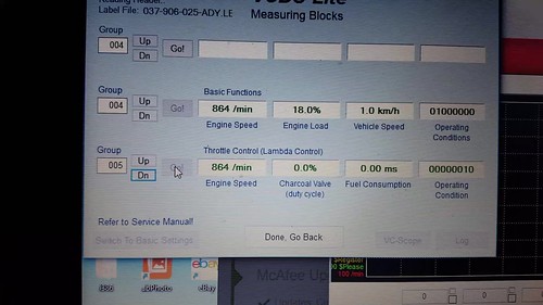 Note the vehicle speed reading in the third box across on the second row. The rattley noise that you can hear in the video is me spinning the speedo over by hand. Circuit is as follows: https://flic.kr/p/R94uPF" rel="nofollow"> 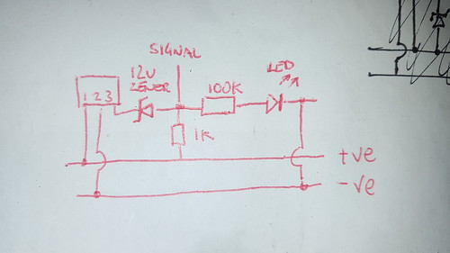 Components are hall sensor, 12v zener diode, 100k resistor, 1k resistor, led. When / if I find my receipt, I'll post the actual part numbers, but there is nothing unusual there. I got mine from CPC components. As I have previously said, I am no expert, but this works. Hall sensor is top left. They have 3 pins, +ve, -ve and signal. The zener diode is a diode that lets current flow the wrong way once the trigger voltage is reached. The way the circuit works is that when the hall sensor is magnetised, it lets the current flow from the positive to the signal pin. When the voltage is sufficient, the zener will let it pass through it. This effectively 'squares up' the signal wave form. Don't think this is strictly necessary for an AGG ecu, but is for a lot of other ecus. The current can then flow through the circuit and give a signal and light the led. I made mine up on a bit of veroboard. No photos of it i am afraid, but it looks pretty similar to my previous one. Takes a bit of thinking about to turn the above circuit into reality, I had about 3 goes! Main thing is to make sure that both of the diodes are the right way round. Hope this helps someone! |
Posted By: club joker 84
Date Posted: 13 Mar 17 at 22:45
Finally, more progress, but also a setback I think  When I last posted, I had got my speed sensor working. Immobiliser coil all seems fine now when the battery is charged, so think that low battery voltage was the problem there. How do you get spare keys cut for these things? Since then, I have sorted out the accelerator cable, and was working on the gear change. Whilst doing this I found that the clutch didn't want to disengage. A bit of investigation showed that the clutch slave was leaking. Darn! New slave and pipes ordered from Brickwerks and fitted. Fortunately I had only recently refitted it all up with new bolts, so this was quite easy. Would imagine it is an absolute bastard with rusty nuts! All bleed, and decided to renew all the fluid and do brakes at the same time. Used a Gunson Eezibleed. Great piece of kit, which made it all straightforward. This was followed by a few tidying up jobs, fitting new speakers etc. whist the van was in the workshop. It's an absolute twat to get in and out of the workshop, so then I had to tidy up after myself to make room to get the van out in the open again. One 4,000 point turn later and the van is out  https://flic.kr/p/SR1Ygu" rel="nofollow"> 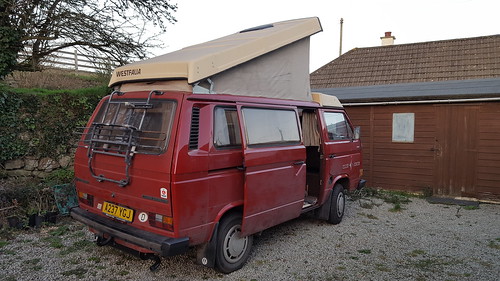 A few things: 1 - van needs a clean and polish! 2 - sounds nice 3 - needs an MOT 4 - gear change needs a bit of adjustment because it goes into reverse without needing to be pushed down - made the manoeuvre out of the workshop quite, err, interesting. 5 - this is the big one. Pretty sure that the headgasket is knackered. A fair bit of white smoke from the exhaust, and also oily water dripping from it. I left it running for about half an hour just to make sure this wasn't just from not having run for a while. When I rev it it sprays oily water (not loads, but enough to mark the gravel behind it. Here's a short video of it running (click the photo to see the video). You can see the smoke levels and a few water drips. Bromy, you can hear how noisy / quiet it is. Sounds a bit diesely on the video, but nicer in the flesh. https://flic.kr/p/SR235S" rel="nofollow"> 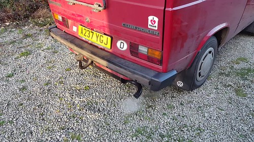 Not really had a head gasket go before, so don't know what I looking at. what do your experts think - is this the head gasket? Anyone had the head off with the engine still in the van? Looks like there is enough room. All the bolts etc. are new, so the most difficult bits should be ok. I knew I should have done it whilst the engine was out, but economised on the £80 gasket! Must be the only thing I didn't do. How do I check if needs skimming, and roughly what does it cost if it does? All help gratefully received!
|
Posted By: jim potter
Date Posted: 14 Mar 17 at 14:04
|
check the oil cooler. they are known to fail. and yes you can do the headgasket with everything in situ. great work so far. ------------- Full vcds ,vag tacho, immo removal ( postal service avalible ), ecu remapping , spanners and a garage for anyone that wants any help, kettle always on. |
Posted By: jim potter
Date Posted: 14 Mar 17 at 14:09
|
also remember you have removed the cat, the engine hasn't been run for ages. check all the levels , run it check them again. any obvious signs of oil in the header tank ? ------------- Full vcds ,vag tacho, immo removal ( postal service avalible ), ecu remapping , spanners and a garage for anyone that wants any help, kettle always on. |
Posted By: rowlesy
Date Posted: 14 Mar 17 at 19:01
|
White smoke is usually water into cylinders might just be wrong or old antifreeze. Don't usually need to skim unless its been cooked - but you'll never know now ------------- UberFukz broke another! sucky sucky five dollah! always out numbered never out gunned! RWS welding 07846 380 467 (worcs) |
Posted By: rowlesy
Date Posted: 14 Mar 17 at 20:18
|
i'd be inclined to give her a good run. you can do a test on the water to see if you have c0 mixed with it. usually the water port at the back fails (cylinder closest the gearbox)- the gasket rots away from the inside out starts off smoking even when hot usually noticeable when stationary then starts pussing gasses into the cooling system creating air pockets - which expand when hot and blows pipes or matrix's depending how bad it gets ------------- UberFukz broke another! sucky sucky five dollah! always out numbered never out gunned! RWS welding 07846 380 467 (worcs) |
Posted By: mrhutch
Date Posted: 14 Mar 17 at 20:28
|
drive it!!! you don't say if it overheats or pressurises the system.. take it out for a burn with a friendly mate on standby for rescue.. it may be fine you need to put some load on it to make a more educated guess.. I reckon it'll be reet ------------- T3 1981 Westy Vanagon - thinks lubricant is a fuel |
Posted By: fufflenarnia
Date Posted: 14 Mar 17 at 20:35
| Whs^^^^^ |
Posted By: club joker 84
Date Posted: 14 Mar 17 at 23:34
|
Thanks for the replies guys. Decided to take it for a burn and see what happened. The good news is that I think you are right Took it for about a 5 mile spin, including a couple of decent hills. Stopped a few times just in case to check exhaust smoke. Once it had got warmed up, the smoke looked much cleaner (it was dark mind, so was using phone torch!), definitely no water drips and it didn't smell oily. Smells a bit 'hot', but that's probably just new paint and stuff settling in. Temperature gauge sat rock steady right in the middle for the whole run, slight increase when I turned the heater off, but no more than that. All looking promising. Will do a proper fluid level check and check for oil / mayo at the weekend when it is light, and put in antifreeze if it looks good. It's just got water in at the moment in case of leaks / head gasket. I didn't want to add £30 of antifreeze to the bill if the head had gone, so have been tight and not put it in yet. Driving a LHD manual took a bit of getting used to again after driving my wife's little automatic Nissan for a year or so, but it soon came back to me. Van felt great and absolutely flies compared to the original engine! Not a rocket ship, but just feels 'right', like it is the engine the van should have had from the start. Just feels more 'modern' and much flexible to drive. It's a great conversion and I'm really pleased with it. Noise-wise it gets loud if you boot it, but nice and quiet when cruising. Think a proper wbx silencer instead of a diesel one would make it even quieter. Most noticeable noise is the fuel pump! It is all on the right rubber mounts, etc. but still quite noticeable. Little bit of fettling to do on the gear change and the clutch is a bit grabby, but is is brand new and I haven't driven a manual much recently, so it might just be me. Bit of a tidy up at the weekend and should all be done at last. If anybody wants to know more or see photos of certain bits, just ask and I'll see if I can help. The conversion is definitely doable for an average home mechanic, and you will learn a lot on the way. You can do it with a reasonably standard toolkit and a cheap engine stand. You do need to fab a few bits here and there, but nothing you can't do with a half decent vice, hacksaw, drill and a couple of files. A mate would be handy for actually getting the engine in and out, but is doable on your own. Working under cover makes this easier, but not essential. You could do the engine build up in a standard garage and fit it on the drive. I have to put my van diagonally in my workshop and open the double doors to get the rear hatch of the van open, so can be done. Just for reference and to give people an idea of costs, I will try to dig out my list of bits, where they came from and how much they were. Thanks again for all your help |
Posted By: mrhutch
Date Posted: 15 Mar 17 at 00:29
|
hold on, there's no mention of my prize? ------------- T3 1981 Westy Vanagon - thinks lubricant is a fuel |
Posted By: rowlesy
Date Posted: 15 Mar 17 at 06:59
|
We know your the gti guru hutch ------------- UberFukz broke another! sucky sucky five dollah! always out numbered never out gunned! RWS welding 07846 380 467 (worcs) |
Posted By: club joker 84
Date Posted: 15 Mar 17 at 23:31
No prizes yet! Not fully sure it works yet! Going to take it to the garage at the weekend and get them to stick the emissions tester in the expansion tank so I know for sure. Prizes on offer when definitely ok. Least i can do is get a round in.  For people who want to know the full cost of everything I have done, it comes to about £2,300. This isn't just engine-related stuff though. There are a few extras in there, like CVs etc., but this includes buying all of the diesel bits. Quite a lot of it was not strictly necessary and just made it look nicer. More still was just refreshing bits like water pump, oil cooler, etc. that i could probably have got away with. It is a pretty thorough list of everything I spent money on, so a good guide to what you could end up spending by the time you have got welding wire, paint, wire, etc. Probably could get it down to about £1,400 and obviously less again if you are already diesel. Cost break down as follows:
|
Posted By: fufflenarnia
Date Posted: 27 Mar 17 at 20:27
| How's things going? Running well? Exhaust noise ok? Impressed??? |
Posted By: rowlesy
Date Posted: 27 Mar 17 at 20:36
|
doubt any of that will need replacing in the next few years so not bad all in.... ------------- UberFukz broke another! sucky sucky five dollah! always out numbered never out gunned! RWS welding 07846 380 467 (worcs) |
Posted By: club joker 84
Date Posted: 27 Mar 17 at 23:44
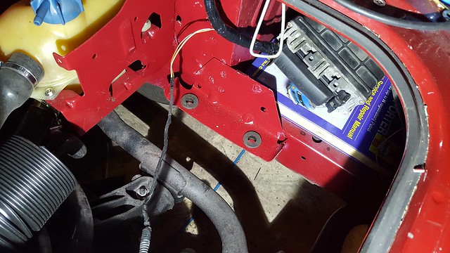
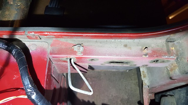
|
Thanks for asking. I have hit a bit of a hold up! Giving the van a pre MOT go over and wash, when I noticed the dreaded behind-the-dildo panel was quite a lot worse than when I last looked. It's been on the 'to do' list since I got the van about 9 years ago, but it has just leapt to No. 1 by rusting right through https://flic.kr/p/Tk1MVv" rel="nofollow"> 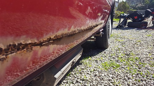 So it needs fixing before MOT time! Back in the workshop and out with http://www.frost.co.uk/car-maintenance-tools-equipment-restoration/automotive-air-tools-power-tools/air-tools-accessories/drill-nibbler-metal-sheet-cutter.html" rel="nofollow - the nibbler (brilliant tool btw!) https://flic.kr/p/S69e1X" rel="nofollow"> 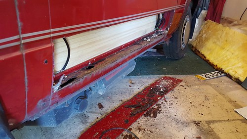 Low panel ordered from Schofields. Very impressed by the quality of the panel. Good shape and nice and thick. Going to do a 'quick fix' for Summer using panel adhesive. Need to actually use the van again! Hoping to get this done in the evenings this week. Bodywork will hopefully get a proper going over in winter, so a quick fix is fine with me. On the cost of the conversion, I don't think it's too bad. It is a full service, new exhaust, cambelt, etc. so like you say nothing should need doing for a while (hopefully ages!). If you added up doing these sort of bits to the DG, you would probably be into the best part of £1k. Like I say, you could definitely do it cheaper.
|
Posted By: fufflenarnia
Date Posted: 16 Apr 17 at 09:05
| Did you find you parts list for the vss? I'm getting my shit together do do my conversion shortly. |
Posted By: club joker 84
Date Posted: 16 Apr 17 at 23:23
|
Hi there, Yes, I did track it down. List as follows, with links: Hall sensor - I bought 2 types, and to be honest I am not sure which I used! They are cheap though, so suggest you get both and see which one works. I will see if I can dig out what I have left and let you know which one I used. First one is http://cpc.farnell.com/allegro-microsystems/a1120eua-t/hall-effect-switch-unipolar-3sip/dp/SC10233?CMP=TREML007-005" rel="nofollow - http://cpc.farnell.com/allegro-microsystems/a1120eua-t/hall-effect-switch-unipolar-3sip/dp/SC10233?CMP=TREML007-005 (£1.12 each) Second one is http://cpc.farnell.com/allegro-microsystems/a1101eua-t/ic-hall-effect-switch-sip-3-1101/dp/SC10230?CMP=TREML007-005" rel="nofollow - http://cpc.farnell.com/allegro-microsystems/a1101eua-t/ic-hall-effect-switch-sip-3-1101/dp/SC10230?CMP=TREML007-005 (£2.60 each) Zener diode - I went for an 11v one in case of any voltage drops etc. in the wiring. http://cpc.farnell.com/nxp/bzx79-c11/diode-zener-500mw-11v/dp/SC05704?CMP=TREML007-005" rel="nofollow - http://cpc.farnell.com/nxp/bzx79-c11/diode-zener-500mw-11v/dp/SC05704?CMP=TREML007-005 (£0.40/10) Resistors - you need 1k and 100k. I bought a bulk pack of 480 different types, but obviously you could buy individual ones for pennies. http://cpc.farnell.com/velleman-sa/k-res-e3/resistor-set-cf-1-4w-5-e3-480pc/dp/RE07594?CMP=TREML007-005" rel="nofollow - http://cpc.farnell.com/velleman-sa/k-res-e3/resistor-set-cf-1-4w-5-e3-480pc/dp/RE07594?CMP=TREML007-005 (£6.64 / pack) Breadboard - http://cpc.farnell.com/multicomp/mc01010/circuit-board-95x72-780-ic-board/dp/PC01289?CMP=TREML007-005" rel="nofollow - http://cpc.farnell.com/multicomp/mc01010/circuit-board-95x72-780-ic-board/dp/PC01289?CMP=TREML007-005 (£0.95 each - probably enough board to make about 10 of them!) LED I already had, but something like this should be ok: http://cpc.farnell.com/kingbright/l-934gd-12v/led-resistor-3mm-green-12v/dp/SC14319" rel="nofollow - http://cpc.farnell.com/kingbright/l-934gd-12v/led-resistor-3mm-green-12v/dp/SC14319 (£0.18 each) Let me know how you get on. Side of the van is fixed, so MOT next week! Will let you know what happens... One I have the MOT (fingers crossed), next plan is to see if I can get cruise control up and running. I have a set of T3 cruise control stalks with the control box and relay. Need new pedal switches (same part number as a T4 and several other VAG models), switch brackets, vacuum hose and an actuator. I have been thinking about using a Land Rover pump and actuator which all looks quite self contained. https://flic.kr/p/TS5RZj" rel="nofollow"> 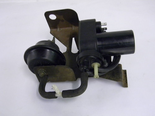 Anyone done anything similar? Any reason that the actuator can't be mounted at the pedal end rather than in the engine bay? |
Posted By: club joker 84
Date Posted: 20 Apr 17 at 23:05
|
Good news, van MOT'd yesterday with no advisories. Taxed it and drove to work today, and van ran great. No issues with temperature etc. so confident no head gasket problems. What a transformation! Engine really suits the van. Plenty of torque. It makes the van much easier to drive, as it's much less fussy about what gear its in. You can even accelerate up hill! Very happy, and a big thank you to everyone who offered help and advice. Much appreciated Ben
|
Posted By: Bromy
Date Posted: 20 Apr 17 at 23:25
|
------------- "follow the masses, do the opposite" |
Posted By: fufflenarnia
Date Posted: 21 Apr 17 at 07:31
|
Good news, and thanks for the component list. You've got more room in the engine bay to mount the cruise control gubbins. It would be difficult to get the connections you need at the front as the cable is under the van by the pedal. |
Posted By: club joker 84
Date Posted: 23 May 17 at 00:01
|
A bit of an update on this, and a bit of head scratching. Firstly, after few days I had my first problem when the van
wouldn’t restart. Battery was flat. As there was no alternator warning light, I
put this down to a dead battery due to the van standing for so long. Put another battery in and all was well for
another couple of days and the same thing happened. Started to have a think about the alternator (still no warning
light though) and stuck a multimeter across it to find that I was only getting
just over 12V, so not charging properly.
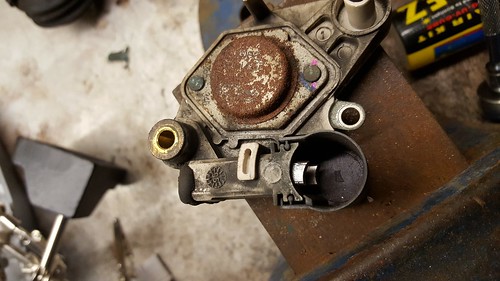
The AGG engine came with a 70A Valeo alternator. Had a read up online and found this useful video https://www.youtube.com/watch?v=f56-26I6idc" rel="nofollow - https://www.youtube.com/watch?v=f56-26I6idc
and thought that I would have a go refurbishing it. Bought a new regulator, flip rings and
bearing from here, came to about £15 http://www.saverepair.com/search?controller=search&orderby=position&orderway=desc&search_query=A11VI66+&submit_search=%EE%98%A5" rel="nofollow - Also an excuse to buy another soldering iron (you need quite
a big one for this). Got this one http://cpc.farnell.com/antex/sr8w270/soldering-iron-100w/dp/SD00837?CMP=TREML007-005" rel="nofollow - http://cpc.farnell.com/antex/sr8w270/soldering-iron-100w/dp/SD00837?CMP=TREML007-005
£14. A bit fiddly, but certainly doable. The bushes and slip rings were definitely
knackered, so I was happy that I had found the problem. https://flic.kr/p/UPrfDo" rel="nofollow"> Knackered bushes. https://flic.kr/p/UPrfXu" rel="nofollow"> Knackered slip rings. It was whilst reassembling it all that I suddenly
twigged that I had been a dopey twat.
Alternators earth through their mounting bolts and body to the engine,
and I had carefully painted over all of this in an effort to make it look
nice! Doh! Anyway, duly reassembled and paint removed around mounts,
put it back on van and added an earth strap for good measure. Tested continuity between alternator body and
van body and had almost no resistance, so all good. Started van up (freshly charged battery), and
found that my alternator warning light was now working (yes!) but that the
alternator was not (noooo!). A bit more reading up on alternators, and found that they need to be ‘excited’ to start charging. The smaller terminal on the alternator needs some voltage sent to it to start things off. This comes via the warning light circuit on the dash. When you turn the ignition on, voltage is sent from the dash to the alternator, triggering the alternator. Once the alternator is working, the voltage 'out' of the alternator is greater than than the voltage in, reversing the current flow and turning off the warning led. I tested this
voltage and found I was only getting about 9v, so started to think this might
not be enough. As a quick check, I very
briefly ran a jumper wire from the large D+ terminal on the alternator to the exciter
terminal, and the engine note instantly changed as the alternator kicked in. Now getting a full 14.5v from the
alternator. Following this initial 'excitement' at a full 12v, the 9v exciter seems to be enough to start it all off. Maybe something to try if anyone else rebuilds there alternator and has trouble? Seems to need a bit more 'kick' first time around. Anyway, problem solved! The moral is don't paint over vital earthing points! Head gasket thing was still nagging at me, so bought one of
the head gasket chemical tester from ebay and found that I did actually have a leak. Bugger.
Undid exhaust, drained fluids, etc. and took the head off. Good news is that there is room to do this with
the engine still in the van. This is a
westie, so the cupboard slightly overhangs, but it is still doable. No obvious signs of any leaks, but gave it a
really thorough clean up (head and block).
New gasket set and head bolts (decent quality) were less than £60, so not too drastic. That
is for a full gasket and seal set, so pretty good value. Seeing as the head was now off, I thought
that I might as well replace the stem seals and clean up the valves. The more agriculturally minded of you will appreciate my ‘ghetto’
valve spring compressor… https://flic.kr/p/UPrcof" rel="nofollow"> It’s a cider press that I made last year out of a fencepost
to deal with some excess apples. A
combination of fence post frame, car jack and a bit of tube. I just put a few shims under the each valve
(i.e. at the bottom of the valves – the cylinder end) and could then compress the
springs and lift out the collets. Bloody
fiddly! More cleaning (dunked the block
in some hot water with Swarfega degreaser and left it an hour or so – came out
sparkling!). Cleaned up the valves (which weren’t too bad) using emery
paper and a drill. https://flic.kr/p/UPregU" rel="nofollow"> Tried more gentle approaches, but this one seems to be the way
forward. Stayed well away from the sealing faces. Was also very careful to keep
everything in the same order! https://flic.kr/p/UPrbYh" rel="nofollow"> Also lapped the valves seeing as it was all apart. Replaced the stem seals. Followed this guy’s videos to put it all back together https://www.youtube.com/watch?v=ILngxEMRw2g&t=4s" rel="nofollow - https://www.youtube.com/watch?v=ILngxEMRw2g&t=4s . Getting the head back on was a bit of twat to be
honest. It is bloody heavy and difficult
to hold over the engine bay. Best done
with a mate I would say. All torqued up
to spec and rest of engine put back together.
Oil and coolant back in (only water so far just in case). Was all super clean, flat faces etc. (measured with a straight edge) so 95% confident the gasket replacement went ok. A lot less bubbling in the coolant tank now, just water being moved by the pump. Took it for a spin and the temperature crept
up to the top of the temperature gauge after about 4 miles. Heaters full on (plenty of hot air coming
out) and temperature hardly moved down at all.
No flashing light, but I was babying it! I noticed that there was a broken fuse to the radiator fan, replaced that and jumped radiator fan switch to turn it permanently on for drive home (was definitely on!). Strange thing was that this made no difference to temp reading, which climbed straight back up. Made it home and had a poke around at the engine. Bottom hose to water pump was staying cool, so I thought thermostat had died. Took it out to see if it made any difference. Pipe now gets warm, but temperature climbed and again, jumping the fan made no real difference. Definitely did not have to put in the full 16lt of coolant, more like 8lt? But it really didn’t seem to be able to take any more, despite doing all the revving it etc. as recommended by Baxter. Rad is bled and hot right to top. Measured blocks using Vagcom whilst it was running and it says that the coolant temperature gets up to about 90degrees when the gauge is up at the top. Jumping the fan brings it down on vagcom pretty quick. Putting on the heater also brings it down. Tested the thermostat that I took out on the stove and it
opened up fine! So, any ideas???? Is this just a temperature gauge
malfunction?? Was ok before all the d1cking
about, but things have been plugged and unplugged a few times since! Or is it
something more serious?? |
 https://flic.kr/p/UPrfDo" rel="nofollow - 20170425_212326
by https://www.flickr.com/photos/57884190@N07/" rel="nofollow - ClubJoker84 , on
Flickr
https://flic.kr/p/UPrfDo" rel="nofollow - 20170425_212326
by https://www.flickr.com/photos/57884190@N07/" rel="nofollow - ClubJoker84 , on
Flickr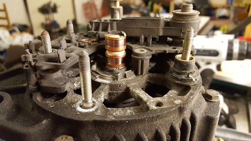 https://flic.kr/p/UPrfXu" rel="nofollow - 20170425_212313
by https://www.flickr.com/photos/57884190@N07/" rel="nofollow - ClubJoker84 , on
Flickr
https://flic.kr/p/UPrfXu" rel="nofollow - 20170425_212313
by https://www.flickr.com/photos/57884190@N07/" rel="nofollow - ClubJoker84 , on
Flickr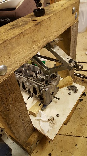 https://flic.kr/p/UPrcof" rel="nofollow - 20170511_232755
by https://www.flickr.com/photos/57884190@N07/" rel="nofollow - ClubJoker84 , on
Flickr
https://flic.kr/p/UPrcof" rel="nofollow - 20170511_232755
by https://www.flickr.com/photos/57884190@N07/" rel="nofollow - ClubJoker84 , on
Flickr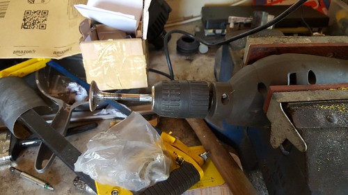 https://flic.kr/p/UPregU" rel="nofollow - 20170507_154906
by https://www.flickr.com/photos/57884190@N07/" rel="nofollow - ClubJoker84 , on
Flickr
https://flic.kr/p/UPregU" rel="nofollow - 20170507_154906
by https://www.flickr.com/photos/57884190@N07/" rel="nofollow - ClubJoker84 , on
Flickr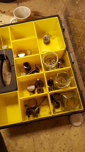 https://flic.kr/p/UPrbYh" rel="nofollow - 20170511_233709 by https://www.flickr.com/photos/57884190@N07/" rel="nofollow - ClubJoker84 , on Flickr
Posted By: bmouthboyo
Date Posted: 28 Jun 18 at 10:52
|
Wow what an amazingly detailed writeup! I am upgrading an existing MK1 Gti conversion in my bus to an AGG soon and this is like gold, thank you. What came of the over heating issue? Did you manage to fix it?
|
Posted By: club joker 84
Date Posted: 04 Jul 18 at 22:52
|
Hi there, Yes, fixed the overheating. It was easy, as it didn't really exist! Took quite a bit of pissing about to find this out though. The voltage regulator in the dash had gone, so too much voltage was going to the gauge and moving it too far. Bought a new one ( http://www.brickwerks.co.uk/voltage-regulator-t3-lt-caddy-instrument-panel.html" rel="nofollow - https://www.brickwerks.co.uk/voltage-regulator-t3-lt-caddy-instrument-panel.html ) and all was well once fitted. Also found out just how little petrol I have been driving around with! Just post on here if you have any questions about the conversion. I will do what I can! It is definitely worth doing the conversion. One thing that I don't think I have mentioned on here is to make sure that your exhaust is good and airtight, at least as far as the lambda. If it leaks then the ecu thinks it is running lean and dumps extra fuel in. Feels ok to drive, but not very economical! Ben
|
Posted By: bmouthboyo
Date Posted: 05 Jul 18 at 07:55
|
Ah that is interesting regarding the voltage regulator. How did you trace the fault down to that? Is there a way of testing the voltage from the sensor with a multimeter? I am looking to install my AGG during August, have not even started the wiring loom yet! Can I ask what you did regarding the oil dipstick? I am not fussed about small hatch access and struggling to source a JX dipstick and tube so looking at possibly keeping the AGG tube and modding the stick? Also do you have any advice / images regarding the air intake? Thanks again for the great writeup.
|
Posted By: Forden341
Date Posted: 05 Jul 18 at 08:17
|
Hi, I am currently running an AGG in a Gipsy and an ABF in a Doka, both using the JX dipstick as it’s a lot more convenient to keep an eye on things through the flap rather than lift the engine hatch, especially with the paranoia that comes with a new conversion! You could as you say extend the AGG dipstick and mark your new level on it no problem tho. Where abouts in the country are you? By your name I wondered if you were Bournemouth as I’m in Weymouth? Cheers, Bert. |
Posted By: club joker 84
Date Posted: 05 Jul 18 at 20:50
|
Voltage regulator I think you just measure between the two connected pins and you should get about 10v. http://www.thesamba.com/vw/forum/viewtopic.php?t=609208&start=0" rel="nofollow - https://www.thesamba.com/vw/forum/viewtopic.php?t=609208&start=0 I only found it because I had tried everything else. New sensor, checking fan function, checking thermostat, etc. Wasted hours! For the cost of the part, it would probably be one of the first things I looked at if it ever happened again. If I did it again, I would probably use the AGG dipstick and just shorten in to get under the hatch. You would probably need to move the collar up it a bit so that it came to the right level with the JX sump on, but much less likely to leak. What did you want to know on the air intake? There is quite a lot of information out there about the different ways people have done it. I was trying to keep it looking factory, so re-used the DG air box. There are two types of DG air box though. I don't think that my method would work with one of the round ones. I aimed to keep the original tubing between the MAF and throttle body, as I thought that these would be the most important bits. Other than that it is just a matter of getting clean, cool air to the MAF. My intake might be a bit restrictive maybe, but the DG filter was quite a bit bigger than the AGG original, so seemed ok to me. Feels fine to drive, but not tried any others to compare. It is nice and quiet if that is important to you. In one of my posts above, there is a link to a guy on retro rides (I think) who managed to re-use the original AGG air box. You will probably need an adaptor to join the MAF to any aftermarket intake hose / filter etc. I used this one http://www.autosiliconehoses.com/air-inlet-adaptor-vw-golf-mk2-mk3-mk4-jetta.html" rel="nofollow - http://www.autosiliconehoses.com/air-inlet-adaptor-vw-golf-mk2-mk3-mk4-jetta.html . It was a bit off when it came, as it was square inside, so I cut this out with a hacksaw and Dremel.
|
Posted By: bmouthboyo
Date Posted: 07 Jul 18 at 08:50
|
That is great thank you, I will have a little look about and check it's not the timing on my older Gti engine and then check regulator. Regarding the air intake, I like your idea of using the intake hoses running to the OS snorkle. What do you use after the airbox up into the snorkle box? I have a diesel snorkle header part but I don't think it will fit in the OS box. How does yours prevent water ingress? Cheers
|
Posted By: club joker 84
Date Posted: 07 Jul 18 at 23:49
|
Hi, No snorkel on mine, just the airbox sitting in the engine bay. Intake faces toward the vent area, but not had any problems with water intake. Pretty sure you could join up to a snorkel if you were offloading a lot. Mine stays on the road, and I have not had any water ingress issues. |
Posted By: Mark-Hans
Date Posted: 29 Aug 19 at 19:14
|
Before you go any further, do you have a wiring diagram of where the impobiliser goes ( I understand the arieal is clipped around the Ignition Switch), where it plugs into the original T3 System and where it ends up?. I am still not clear 'what' the imobiliser, imobolises?..... I think this system I am trying to sort has taken a nasty high current shock, but no one actually has a wiring diagram of the T3 original wiring to the Golf GTi set up. Mabye you have one?, would be very very helpful to know. My computer is a Digifant 11, 037 9906 022 N. Any electrical information would be a great help!. Thanks in advance. Mark ------------- Mark..Amsterdam |
Posted By: club joker 84
Date Posted: 29 Aug 19 at 23:22
|
My ECU is a Simos unit, but I think that the immob wiring is probably similar. There are only 6 wires to the immobiliser. 3 of these are from the immobiliser aerial ring and plug straight in. The others are a 12v, earth and a grey and white wire that needs to be connected to pin 43 on the ecu (may be different on your ECU). I ran a new wire from front to back for this. The 12v can be taken straight from a spare terminal on the fuse box. Note that the immobiliser seems to be a bit picky about earths, so make sure that you get a really good connection to the body. Hope this helps! Ben
|
Posted By: club joker 84
Date Posted: 29 Aug 19 at 23:32
|
Should have said, the factory immobiliser lets the engine fire up 'fully' (i.e. with spark etc) for a few seconds before it cuts it off. This is to help you differentiate between immobiliser issues and general running issues. Assuming yours is a factory immobiliser, then it will fire up ok but then die. If it is not doing this then your problems probably lie elsewhere.
|
Posted By: Mark-Hans
Date Posted: 30 Aug 19 at 07:19
|
THANK YOU. You are the first person to give me such useful information. So, the engine will spark for a few rotations and then shut down. This is triggered by the one wire you ran from front to back!..... OK, as you know this much, then I'll throw a couple more...... :-) If the main coil feed looses it's earth, i.e., from the Coil HT outlet, then what will it blow up!.......... no spark at all still!. The Computer seems my only choice?....... If you have any other diagnosis tips, I'd love to hear them. Greetings and thanks from Sunny Amsterdam. ------------- Mark..Amsterdam |