1.6CS to AEF Engine Swap
Printed From: The Brick-yard
Category: T3 Section
Forum Name: T3 Engine Upgrades
Forum Description: Forum for tuned or alternative engines.
URL: http://www.brick-yard.co.uk/forum/forum_posts.asp?TID=52595
Printed Date: 19 Apr 24 at 07:50
Software Version: Web Wiz Forums 12.06 - https://www.webwizforums.com
Topic: 1.6CS to AEF Engine Swap
Posted By: colinthefox
Subject: 1.6CS to AEF Engine Swap
Date Posted: 26 Apr 10 at 22:44
|
1.6D CS engine to 1.9D AEF SWAP I wanted to swap the 1.6D CS engine in my T3 Autohomes Kamper for a 1.9D, because the 1.6, although it was a full recon with 10k miles only, would not keep 90kph up motorway inclines in UK and more particularly Europe. It's important for safety to stay ahead of the trucks, and we have come across some seriously steep inclines on two lane motorways in Germany and Spain where trucks aren't permitted to overtake. They get very irritated when baulked by a campervan, and in one case a Portuguese trucker tried to physically sweep us off the road. We don't need more speed on the flat as we're quite happy to cruise at 62MPH (100kph). Our journey times seem to be more about keeping going and avoiding jams than about top speed. The aim was to end up with a van that would be as reliable as it was before, with no compromises on engineering integrity. So every aspect of the swap was investigated with reliability and simplicity (and possible improvement) in mind. I had been pleasantly surprised at the 15% estimated improvement we got by reducing weight and air resistance by replacing the old Autohomes Kamper pop-top with a sleeker, lighter version. The 1.9 engine would give a further 24% increase in torque as standard, and with improved breathing could probably be upfuelled by another 5-10% without too much smoke. Altogether that's a 50% improvement on the original spec. I was aware that the van would probably feel undergeared if I kept the original transmission, but didn't want to trade off hill climbing ability for top speed. I could always decide later whether to trade some of the torque for top speed by longer gearing or taller tyres. Which engine to choose? Either a 1Y or an AEF are normally aspirated 1.9 diesels built on similar block and cylinder head to the CS. Either would give 64bhp against the 54bhp of the CS, and the increased torque would be in a similar rev range to the old engine. 1Ys and AEFs have a throttle cable so will operate without electronics. A turbo would give more power, but at lower revs, necessitating a change of gearbox, and the engineering complexities and reliability issues of cooling oil, water and intake air. All that ruled a turbo engine right out for me. Other issues might be engine mounts, and interference with the engine bay cover. Also I'd want whatever I ended up with to be understood by Pierre, Fritz, Paulo, Dave, or whichever mechanic was called upon to repair it in my absence. So I looked for 1Y and AEF engines at car breakers, and on a well-known internet auction site. Breakers had no 1Ys, but all had AEFs, already removed from donor vehicles. I found an AEF locally on ebay, and was able to see it running in the donor Polo. Cost me less than £200 for an 80k engine. The reconditioned CS engine that was in my van cost me £1200. To me that's a bit of a no-brainer, if you're prepared to take the risk of a used engine, it has to be better value. I'm going to describe all the issues I came across, one by one, with the solutions I came up with, and the thinking behind the decisions. My apologies if I'm teaching some of you stuff you already know, and much of the knowledge has been gained from too many other people to acknowledge here. I wanted to gather ALL the information for this particular swap together in one place. This is not a set of instructions. Information and opinions are provided in the spirit of being helpful, everyone should interpret and use the information carefully and safely according to their own circumstances. I have assumed that you have suitable skills to do a like-for-like engine replacement. Some minor welding and simple metal fabrication skills are required, as is the ability to do some reliable electrical wiring. All the information provided relates to the differences between the two engines. I don't claim to know all the answers either. Please, if any of this is wrong, or can be improved, then add your bit. Where I know my knowledge is skinny, I've asked for more info. If I'm talking b*ll*cks please tell me, I won't be offended. BUYING THE NEW ENGINE Try and see it running in the donor vehicle. Polo cars are likely to have been more gently treated and have lower mileage than vans or pickups. The new engine needs to be complete with diesel injection equipment. Most that I have seen being sold by scrappers are sold without the pump. You can't easily use your old Bosch injection pump on these engines. Try to get the engine with all ancillaries and bits and pieces that connect to it. As`well as all the diesel injection gear, you will need the alternator (plus connectors and a few inches of cables), water pump housing and pump, power steering pump with connections (even if you don't have power steering), belt tensioner, fuel pipes, cam cover breather, cam belt covers, crank damper/pulley, oil filter housing. You will not require the flywheel, dipstick, or sump, except that the dipstick and sump will protect the engine against dirt, till it is installed. You also won't need the electronic controller, or the key and transponder.
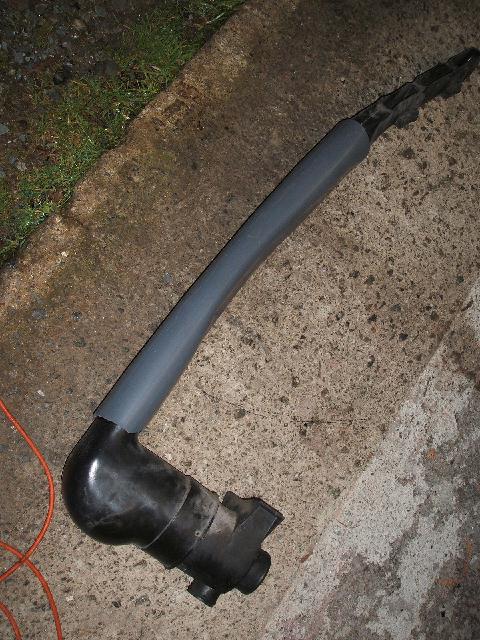
INLET TRACT The air inlet system is important for noise reduction, and for providing the maximum quantity of cool air for combustion. It is situated in the left hand duct rising at the side of the engine compartment. The original is quite well designed in that it takes air from a high pressure point in an air scoop generated by vehicle forward motion, just behind the grille, but on mine, the corrugated tube leading down to the plastic bend was broken and appeared woefully inadequate in cross section for even the 1.6, let alone a 1.9. Intake breathing is very important for minimising smoke and maximising power in a NA diesel. I re-used the original plastic top terminal, used a bit of wood to wedge the intakes open a bit and used a heat gun to reset the plastic. I threw away the corrugated tube and replaced it with a 600mm long piece of 90mm builders PVC duct (bummed from a contractor burying telephone cable ducts) which I reshaped to an oval section and bent slightly with the heat gun, so that it fitted in the void without touching the sides. A bit fiddly to install over the bottom bend and the air scoop, and seal with silicone, but it gave a slight increase in speed at the top of my test hill, even with the old 1.6 engine.
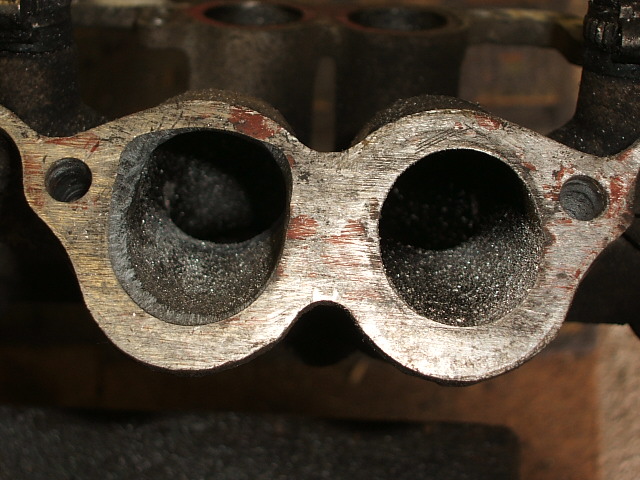
I used the intake manifold, air box, and filter from the CS, as it was all easy to fit, cleared the chassis, (just) and was easy to make air and noise tight with the original intake air tract. The oval ports on the CS manifold didn't match exactly with the D shaped ports on the AEF engine, so I made a token attempt at matching them (and the manifold gasket) using a round file. On the left is the modified port, the original on the right. http://www.windsorchair.co.uk/vwpictures/AEFEngine/XXXXXXX.JPG"> There is not enough metal on the inlet manifold to do full accurate port matching, but every little helps on the inlet side. I also cleaned the engine of all the crud deposited in the inlet ports by the EGR valve, making sure the valves were closed before cleaning the ports. I used the CS inlet manifold gasket as it fitted much better than the new 1.9 gasket.
Important that the whole inlet system is leakproof to prevent noise breakout. The new setup gave a very slight increase in noise inside the van as the old corrugated tube had a built-in noise attenuator, and my PVC pipe did not, but I sorted that by fitting soundproofing to the inside of the vertical air duct. The noise outside the van was noticeably more, but I'm not so fussed about that. The air filter box is 12mm further to the left and slightly higher due to the slightly taller engine block. So I had to fabricate a couple of wiring clips to raise the wiring harness a couple of inches to clear. I slightly modified the profile of the inner skin of the wheel arch at the front of the air filter box with a lump of wood and a big hammer, and used any tolerance in the engine mounts to move it as far to the right as possible. The aim was to have about 15mm clearance round the air box. 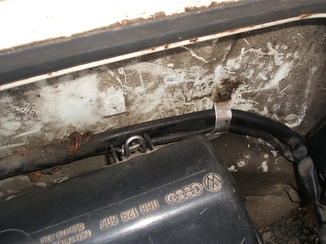 EXHAUST SYSTEM
The choice was between the original CS exhaust manifold and system complete, or I could have used the AEF manifold and fabricated a pipe using the AEF flange, with larger diameter tube coupled to an Early 1.6TD silencer, which would mount on the original points. Of course I would have to blank off the old EGR valve flange on the manifold too. Seemed like a lot of work for not much gain. Although the larger diameter system would present less resistance to exhaust gases, and hence promise slightly better performance, I reckoned the difference would be minimal. I opted for the original CS system complete, as I couldn't be bothered to do the fabrication, and if a special broke, no-one would be able to supply a new one off the shelf. So I fettled the manifold to improve the gas flow a little, and left it at that. Oh, and one other thing while we're on the exhaust system.....because of the taller engine the exhaust needs adjusting (pulling out by 12mm) at the joint between the downpipe and the silencer. If this joint is rusted solid a complete new exhaust will be required, cos it won't fit! Perhaps when this exhaust eventually needs replacing, I'll have a go at evaluating a custom system.
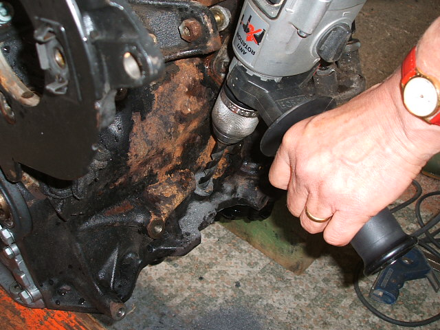
DIP STICK The AEF dipstick is on the wrong side of the engine, so I blanked off the old hole by tapping it 12mm and inserting an Allen headed bolt with loctite 271 sealant on the thread, and for good measure a fibre washer under the head. The new dipstick hole was drilled through the thoughtfully provided boss on the other side of the engine with an ordinary electric drill, while the injection pump was off the engine. I drilled a 12mm hole to a depth of 17.5mm to the shoulder, then changed to a 10mm drill to go right through. I snapped the drill because I didn't use a backing block to ease the breakthrough. http://www.windsorchair.co.uk/vwpictures/AEFEngine/XXXXXXX.JPG"> That's Mrs CtF putting in an appearance by the way.  I chamfered the top edge so the dipstick O ring would slip in easily, then installed the dipstick and tube and measured the distance below the sump flange, and compared it with the old engine. Depth of the hole was spot on. The tube had to be bent away from the block slightly to clear the bypass hose. With hindsight I realise I could have drilled the hole at a slight angle to save having to bend the tube. The original tube fixing bracket was ground off and a new one welded on nearer the top of the tube, using the bolt where the water pump bracket fixes to the injection pump bracket.
FLYWHEEL/CLUTCH I used the original CS flywheel, with new bolts of course. Very important to install and grease a new spigot bearing in the end of the crank, as the AEF doesn't have one in the Polo application. The CS clutch should easily be able to cope with the extra torque, and had only done 10k so I re-used it. Normally I would put a new clutch in as a matter of course. Oh, and I fitted a new input shaft oil seal in the gearbox. SUMP etc Because the engine will lean over at a greater angle than in the Polo, the CS cast sump, and the oil pump pick up pipe must be used, with a thin sump gasket. I used the rubber gasket from Brickwerks, which is a bit thicker than the standard version, but just fits. The AEF windage tray (that's the steel pressing with the rubber sump gasket) is too thick and cannot be used, as the bellhousing bolt holes into the end of the sump won't line up with this fitted. This sump gasket is below the oil level so must be a good seal. CAM COVER The AEF cam cover must be used, complete with the filler cap, and this will have to be used for oil fill due to the oil fill pipe being fouled by one of the auxiliary belt pulleys. I removed the whole oil filler pipe and fitted a fabricated blanking plate using the original gasket. The engine breather must be connected to the inlet manifold, using the CS rubber pipe at the manifold end, and the AEF pipe at the cam cover end. I cut the rubber pipe and used a plumbers 15mm copper end feed capillary straight joint inside the rubber pipe, then pushed the reinforced end inside the plastic AEF pipe with a jubilee clip to connect the two.
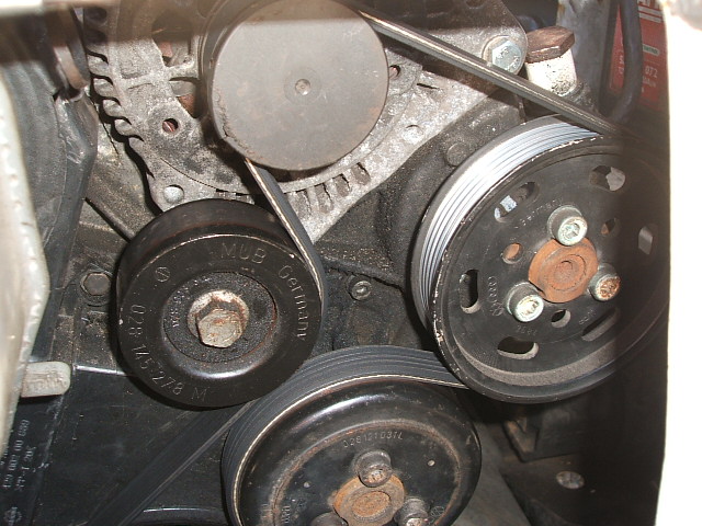
WATER PUMP AND ALTERNATOR ETC I would have liked to use the original vee belt setup with the T3 water pump and alternator etc for the sake of originality, but although it looked like it would all fit, the mounting bosses on the AEF block make this quite impossible, so I had to use to use the AEF water pump/alternator/flat ribbed belt setup complete. This setup needs an idler pulley at the power steering pump position, or the belt rubs against itself at the tensioner position, so I removed the vanes and stator from the PAS pump, filled it with oil and blanked off the connections. The auxiliaries belt is a 5PK1220. This is quite a neat setup and all fits snugly and well below the engine hatch lid, but the PAS pulley fouls the oil filler tube, so the tube has to be removed, and the hole in the sump blanked off. I used a piece of scrap, cut and drilled to the shape of the original flange, with the original gasket. The much improved grip of the ribbed flat belts on the pulleys together with the angular momentum of the rapidly rotating alternator has introduced problems, resulting in auxiliary belt, tensioner and crank nose failures for many engine makers, and not just VW. All beyond the scope of this thread, but you can search the internet for "overunning alternator pulley" to find out more about this problem. I managed to find an alternator with a clutched pulley, so shouldn't have this problem, I hope. It is important to make sure the crank bolt is tight, and new if it has been removed.
INJECTION PUMP The AEF engine uses the Lucas injection pump, whereas the CS and most of the others use the Bosch. This Lucas pump has been given a pretty bad press in these kinds of forums, but my diesel specialist says that although he prefers the Bosch (he's a Bosch agent after all), the Lucas does the job perfectly OK. That's as long as you stick to standard diesel, and don't use Bio, or try and wind up the pump to deliver loads more fuel (ie turbo etc). After all there's plenty of French filth out there running around on Lucas pumps and doing high mileages. Can't be that bad then. It is necessary to remove the immobiliser from the injection pump, and to do this the pump has to be removed from the engine. Before doing this components must be accurately marked for replacement positions. I used a Stanley knife to make accurate scribe marks on pump flange/bracket, and on the pump boss/sprocket. Although the pump mounting holes are not design to be adjustable, there is enough play to make a difference, so I marked the flange to bracket position. I made TDC marks with tippex on pump sprocket/bracket, on crank sprocket/engine and on cam sprocket/engine. Then the tensioner and timing belt were removed followed by the three bolts holding the pump sprocket to the boss. Don't under any circumstances loosen the centre nut, or the basic timing setting of the pump will be lost, and you'll have to take it to a diesel injection specialist to get it reset. Remove the four steel injection pipes as two pairs. The injection pump can then be taken off for modification. The AEF engine was designed to be managed from an electronic controller, which controls five items:-
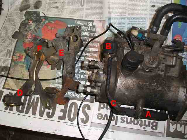
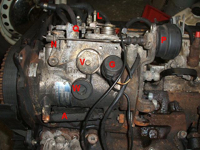
My experience with the transplanted engine has revealed that the commencement of injection valve (grey/yellow wire) needs to be operational for about 10-20 seconds after starting from cold, to avoid spluttering and white smoke on startup. This can be achieved either with a delay-off timer which is triggered by the starter motor signal, or by a manual switch in the cab. The standard glow plug relay works well for cold starts, but the AEF needs a short glow even with the engine warm. This can be achieved by adding a resistor to the glow plug sensor wiring. First I tried 470ohm but this wasn't quite enough. Two of these (940ohm) seemed a bit too much, but I haven't tried any values in between yet. I reckon about 600ohm would be about right. These are the various parts of the injection pump:-
A is the immobilser which can be removed once the pump has been taken off the engine. For security it is designed not to come off unless the pump is removed. You will need to connect the stop solenoid B, so disconnect the wires at the immobilser at C. D is the anti-theft bracket and can be removed from the pump bracket E by removing the security bolt F. This allows you to get at the wiring to connect it after you've put it all back on the engine. 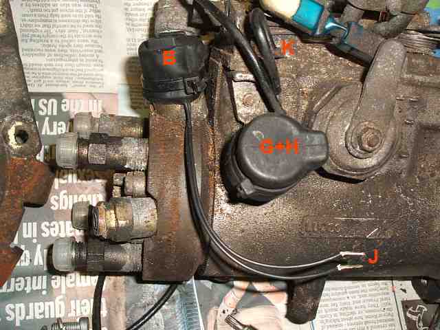 G+H are the two solenoids which were controlled by the electronics on the AEF. (One is round the other side of the pump out of sight). The one with the grey/yellow wire is the "commencement of injection" valve. The one with the yellow/green wire is the "full throttle stop solenoid". The fuel cut off solenoid wires at J are the ones you need to connect to get the pump to work. One goes to ground. Point K is a convenient place. The other connects to the black wire (ignition) from the van.
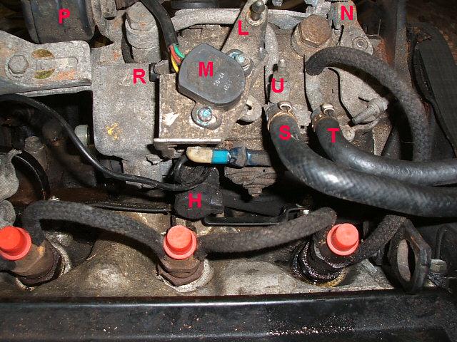
L is the throttle lever, and must be retained. M is the throttle position sensor for the electronics, and is discarded, along with the bracket. N is the high idle lever. Can be left in place but disconnected from the vacuum actuator. By default, the spring pushes this lever towards the "High Idle" position, so it should be tied against the spring pressure with wire. P is the high idle vacuum activator, for boosting the idle speed against loads such as air conditioning. As we don't have aircon this can be discarded. The bracket would interfere with the engine hatch cover anyway, so should be cut off, as in the after photo. Q is the idle adjustment screw R is the max revs adjustment screw (only for the brave!) S Supply fuel pipe T Return fuel pipe U Nipple for sucking fuel up to the pump. V Air bleed screw W Max fuel adjustment is inside this plastic cap
 Following modification as above, and after drilling the dipstick hole in the engine block, I refitted the injection pump and sprocket, lining up the scribe marks. Then I fitted the old timing belt, (tell you why later) lining up the tippex marks. Injection pipes were refitted leaving the injector unions slack.
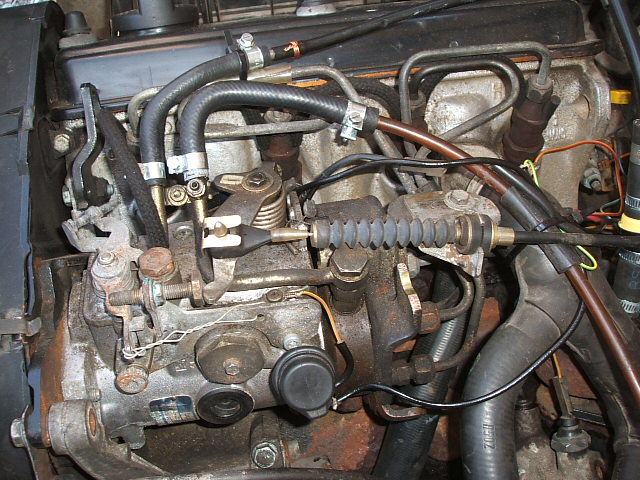
For timing of the belt, see other threads on this forum, or a Haynes manual for VW Polo (Haynes manual No. 3500). The only special thing about the Lucas pump is the use of a 6mm dowel to set it at TDC, otherwise setting the crank and cam at TDC is exactly as for all the other VW diesels. This is a photo of the finished pump as installed.
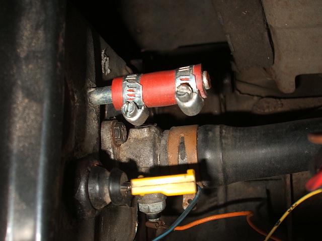
DIESEL PIPES I kept the two rubber elbows complete, which connect to the injection pump, but rotated to face to the back of the engine, and with new fuel hose clips. The fat one is the supply, and the thin one the return. I had to slacken the banjo on top of the fuel filter, and swivel it round a bit. The clear pipe from the filter connects to the supply, and the black one to the return. Both need metal inserts. I cut the intake rubber elbow down for a neater job. These pipes must be adequately supported with zip ties to stop them vibrating, and anywhere they pass near other pipes they should be sleeved with short lengths of suitable rubber tube. The steel injector pipes MUST be refitted with the plastic anti vibration clips, or they will quickly fracture. THROTTLE CABLE The CS throttle cable is used, with slight modification. I drilled right through the plastic blob at the end, and used a spring clip to hold it on the pin. This increased the clearance from the hatch cover, which is pretty minimal at this point. The bracket for the grommet has to be modified by cutting and shutting to provide clearance from the hatch cover. This bracket should be 125mm from the throttle lever pin at mid adjustment, then the cable doesn't need adjusting under the cab floor at the front of the van. Once I had this set up, I modified a spare cable to match so I won't get caught out if it breaks. To further increase clearance from the hatch cover, I bent both the throttle lever and the bracket for the grommet downwards a bit. Even then, when I ran the engine these bits rubbed slightly on the foam under the hatch cover, so I removed a small amount of sound insulation from it at this position.
COLD START BOWDEN CABLE This is not needed, so can be removed. I tied it out of the way in the space over the transmission, as it looked difficult to remove completely. This has also removed an annoying engine related ticking noise in the cab, incidentally.
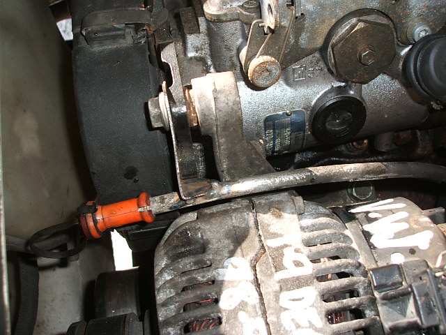
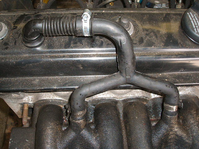
COOLING SYSTEM Cooling system is absolutely as standard, but will have to be in top condition to cope with the extra load imposed by the larger engine. I used the cast alloy hose flanges from the CS cylinder head, because they have the temperature senders built in. All hoses can be reused from the CS without modification, apart from the bypass hose, which needs trimming at the bottom to provide better clearance from the dipstick tube, and because the AEF water pump outlets are a bit further back than the CS ones.
On my engine there was a 8mm steel vent pipe sticking out of the rear of the cylinder head, and this isn't needed, but it wasn't easily removed, so I made a cap out of a length of 8mm tube, with a plug in the end and two jubilee clips.
I used the oil filter housing and oil cooler off the AEF, as the CS one is different. These housings never seem to have a flat face to seal against the block, so I lapped it flat with fine emery paper on a sheet of glass, before bolting it up. Thermostat should be installed with the arms top and bottom, to get the best coolant flow horizontally past the sensing element. I should have known better than to reuse the old one....it was letting by, and I had to drain down to fit a new one. Thermostat cover needs to have an angled outlet to clear the engine mount. Either the CS or AEF one will work. I have left the original radiator for now, to see if it is adequate for the new engine on long summer climbs. We'll see. Most important to check the operation of the fan thermoswitch to avoid overheating problems. Before removing the old engine, I got the engine nice and hot, and left it idling to ensure that I could hear the fan cutting in and out. VACUUM PUMP The vacuum pump has to be from the AEF, because it's a different fitting to the CS one. The non return valve on my vacuum pump was broken, and because I was too tight to buy a new one, I punched out the broken NRV and welded a 12mm pipe stub on to the vacuum pump lid. Then I used a generic NRV (from a type 2 van) with a couple of lengths of vacuum tube and jubilee clips. Works great!
ELECTRICAL ITEMS All unwanted wiring was removed from the AEF engine as discussed above. The only wires remaining should be those from the three injection pump solenoids. Label all the wires connecting to the old CS engine so you can replace them all in exactly the same place on the new engine. Reuse all the various sensors in the same places. In particular, the oil pressure switches, which look very much the same, should be replaced in their original positions. The 0.3 bar oil pressure switch goes in the blanked off hole at the back of the cylinder head. There are two pressure switches in the oil filter housing, the one with two connections is removed and the blank previously removed from the cylinder head I used to blank off the outlet. The "buzzer of doom" 0.9 bar pressure switch goes in the other boss in place of the existing one. Confused? I was. I got it wrong initially, and had the BoD frightening me on starting the new engine. The alternator has to be from the AEF, preferably with a clutched pulley. I fitted a new regulator as a precaution. I had to join the connectors on the alternator to the wiring on the van, by soldering the wires together, then shrink sleeving overall. (that's why you need the cable ends with your alternator) I scraped a clean surface on the water pump housing mounting to connect the engine earthing strap. Important to replace the zip tie securing the two wires to the starter solenoid, to prevent the connections failing. Coolant temperature sensors are transferred with the cast alloy hose flanges off the CS. I scraped the surface of the water flanges under the bolt heads, as I couldn't get earth continuity (weird). INJECTION PUMP ELECTRICS. The short wire which used to go to the immobiliser from the fuel stop solenoid connects to the black wire on the van. The other side of the solenoid goes to ground at one of the fuel pump cover screws.
Grey/yellow wire goes to the new cold start relay. I used a washer delay relay from an old Vol-vo, and modified it to give a longer delay. It activates the "commencement of injection" solenoid for 20 seconds after the starter is used. Any "delay-off" relay would be suitable, but I couldn't find one on offer, so I was forced to make my own. The solenoid could just as easily be operated by a manual switch and indicator light in the cab, but I didn't want to run the extra wire. Without this solenoid, cold starts are accompanied by spluttering, and some white smoke, and I was too late to try any well below freezing starts.
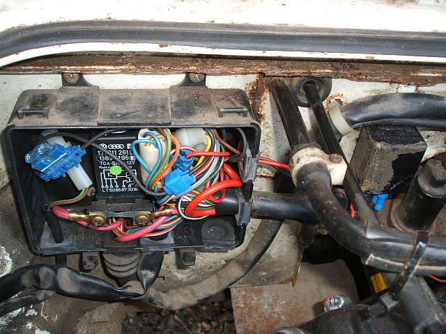
The connections were made, and the fuse added, in the black box that houses the glow plug relay, and the new relay added to the bulkhead nearby.
 I left the green/yellow wire to the "full throttle stop solenoid" in place, but tied it out of the way in case I find a use for it any time. OIL COOLER The oil cooler off either engine will fit OK., making sure the coolant pipes are orientated correctly. ENGINE MOUNTS These are a direct swap from the CS. I had to use a tap to clean up the threads on most of the engine block mounting holes, as being unused till now, they were full of crud. Useful to do this before fitting the engine! TIMING BELT COVERS I used the timing belt guards from the AEF, including the cast alloy bit in the middle. Although not as neat in this application as the CS guards, the CS ones won't fit because the injection pump bracket for the Lucas pump is different (and far better). THE COMPLETED INSTALLATION The photo is high resolution and too big for the forum so here's a link. http://www.windsorchair.co.uk/vwpictures/AEFEngine/2010_0426enginebay.JPG - http://www.windsorchair.co.uk/vwpictures/AEFEngine/2010_0426enginebay.JPG
INITIAL STARTING
After filling with coolant and oil (I have taken to pre-filling the oil filter before I screw it on), I removed the vacuum pump and wound the oil pump clockwise with a squashed piece of 15mm copper piping until I felt it really pumping oil. Then I replaced the vacuum pump. If you just connect up and operate the starter, you will have a flat battery and burnt out motor long before the engine runs. It is absolutely vital to prime the diesel injection system properly. Here's how I did it. I set the engine at TDC No.1 cylinder and took off the old timing belt. Here's the pump at TDC No.1 with a 6mm dowel inserted in the hole in the pump boss.
After connecting a bit of transparent tube to the nipple on the injection pump supply line, I sucked up diesel from the fuel filter to the injection pump, then closed the nipple. I did this several times till the pipe stayed full. Then I wound the pump clockwise with a stick in the pulley until I could hear and feel that the pump was full. There is a bleed screw on the side, and I loosened this one till fuel squirted out with no air. Next I made sure the injector unions were all slack, turned on the ignition and wound the pump until fuel squirted out of all the injector unions, before finally tightening the injector unions. With the ignition on, at this point it shouldn't be possible to turn the pump by hand because it is full of fuel right up to the injectors. With the ignition off again, I positioned the pump at TDC No.1 and inserted the timing dowel. Then I fitted the new timing belt. Instructions elsewhere. You know the form by now.....Cam setting tool, clutch timing mark in the little bellhousing window, dowel in the pump. Normal timing belt fitting. Then it was on with the belt covers, crank pulley, belts etc. Then I disconnected the fuel cut-off solenoid and gave the starter a blast, to check it all went round OK with no funny noises. Also pressed the clutch to let it centralise. Finally with fuel cut-off solenoid reconnected, turned the starter and it started first time. No smoke, and no issues till I revved it up and the "buzzer of Doom" kicked in. But that was just because I had the wrong switch on that circuit. However, when it was warm, it wouldn't start because I found it needed a shot of glowplug, so I had to modify the glow plug wiring. The next day, in the cold, it spluttered and smoked, so I had to connect the "commencement of injection" solenoid via a timer all as mentioned previously. Now it starts every time, first time, so I will set about fine tuning the glowplug resistor to minimise glow time, whilst retaining reliable starting. THE RESULTS On driving the van, the difference was immediately apparent. Much more torque is available as expected, and I could drive the van without revving the nuts off the engine to get it into the next gear up. So generally, driving is much more civilised and quieter on normal roads. However, with the same gearing, the cruising speed is still 62mph, so on the motorway the engine is doing exactly the same revs as before. But it will climb hills generally one gear up from what it used to, and there isn't a hill on the UK motorway network that it won't tackle at more than 56MPH, and that's faster than the trucks, so never again will I have a truck right up my chuff at the start of every incline. Not sure about MPG yet, as I haven't done enough miles. I'm really pleased, and can recommend the swap to anyone needing to change a knackered CS. You might also consider it as an upgrade for a decent engine too. ------------- 1.9D AEF T3 Kamper All sorts of other oil burners too. |
Replies:
Posted By: mrhutch
Date Posted: 27 Apr 10 at 00:15
|
fantastic write up chap... a genuine resource for those considering diesel upgrades... now stick a f**king turbo on it! ------------- T3 1981 Westy Vanagon - thinks lubricant is a fuel |
Posted By: rolo
Date Posted: 27 Apr 10 at 07:33
|
Nice one Colin. ------------- the last one |
Posted By: Garrick T
Date Posted: 03 May 10 at 22:54
|
i also converted to an AEF a few years back, and even though the bhp increase seemed marginal the difference in driving has been fantastic. Ended up changing my gearbox too to a 3H for a better final drive which has given me much better motorway crusing and I always return over 35mpg which i think is pretty damm good.
------------- Fun Lovin Flat 4's V-Dub Club Telford |
Posted By: pictonroad
Date Posted: 10 May 10 at 16:54
|
Wow, what a write up. ------------- On the South Coast.... |
Posted By: eddiegaskit
Date Posted: 31 May 10 at 23:46
|
What can I say?....Excellent write up, major help for my AEF fitting this weekend !.....It wouldn't start after plumbing and fiting so I googled for a solution and hey presto....Here I am , and it's running nicely !!.....I would have never found the immobiliser if it wasnt for you !...Incidently, I removed it with a hammer and screwdriver easily with the pump in the van attached ! ....I will be driving to work tmrw in the van so fingers crossed for the maiden voyage !! |
Posted By: colinthefox
Date Posted: 01 Jun 10 at 23:20
|
Pleased to be of assistance. I didn't have the nerve to smash off the immobiliser though. I've just prepared my "spare" engine a couple of weeks ago, and it only took minutes this time!
Just done 550 miles in one day, and the van never missed a beat. ------------- 1.9D AEF T3 Kamper All sorts of other oil burners too. |
Posted By: jtwhitestar
Date Posted: 02 Jun 10 at 23:22
|
would it be rude to ask more question about the pump wiring i have have a 1.9 aef, the bus started out as a jx. i bought the van with the conversion done, i have a lot of smoke on cold start and have to crank it over to start when warm. i just dont understand the relays you mention. will talk to friends but any help would be good. ps mine will happily keep up with a jx jt
|
Posted By: colinthefox
Date Posted: 03 Jun 10 at 18:21
|
Things happening here......more info on relays tomorrow. ------------- 1.9D AEF T3 Kamper All sorts of other oil burners too. |
Posted By: colinthefox
Date Posted: 04 Jun 10 at 19:53
|
OK....about the relay.
There's only one extra relay on my setup. That is a "delay off" (delay off means that it stays on for a specified period after something else has happened) relay operating the "commencement of injection solenoid" (that's the one with the grey/yellow wire). The relay stays on for 20 seconds after the starter has been operated, and while it is energised, the solenoid advances the ignition just like the cold start lever did on the JX. You could of course just do this with a push button in the cab instead of the relay, with a wire leading to the solenoid, and hold it in manually for a bit when you start the engine. To prove this to yourself, you could try just connecting the grey/yellow wire to the battery + terminal, then start the engine from cold. It should start without smoke, (but with a much more diesely sound!) and after a few seconds you can disconnect it again and the engine will quieten down. Not very convenient for every day though, that's why you need a relay or push button.
The other electrical bit is the 600ohm resistor in series with the glowplug sensor. You can get one of these from an electronics store like Maplins, (I ripped one out of an old breadmaker cicuit board). You need to solder wires on each end of the resisitor, then a male and a female spade connector on the wires, wrap it all up in shrink sleeving or electricians tape, tie wrap it to the wiring harness, and connect the female to the sensor and the male to the wire to the glowplug relay. (the sensor is the one in the water flange at the very back of the cylinder head). The resistor fools the glowplug relay into staying on a bit longer, and to giving a short glow even with a warm engine.
Hope this helps. That's about as detailed as I can get. ------------- 1.9D AEF T3 Kamper All sorts of other oil burners too. |
Posted By: jtwhitestar
Date Posted: 08 Jun 10 at 21:48
|
People like you are heros i could have spent a fortune finding these problems, tried advance solanoid with battery connection instant result. have now put a switch in the cab for time being and i no longer have the mass amount of white smoke and lumpy running when cold next stop 600ohm resistor in series with the glowplug sensor. thanks you are a star. jt
|
Posted By: 2435mick
Date Posted: 12 Jun 10 at 15:13
|
What an impressive write up, I have spent weeks, nay months trying to get to grips with my AEF (which incidentally was already fitted in my van when I bought it), I do still have one or two issues though, what wires need to go to what terminal (ie, oil pressure switches, temp senders etc). I have studied your photo and this has helped tremendously, any chance of one or two more to identify what goes to the expansion bottle, oil and so on. ------------- I didn't do it.....honest |
Posted By: colinthefox
Date Posted: 13 Jun 10 at 20:44
|
The issues you mention aren't to do with the AEF, they are the same as for the original engine, so not covered here. The Haynes manual wiring diagrams 12.29 and 12.30 show those wires. I know the Haynes only does petrol vans, but they should be the same. ------------- 1.9D AEF T3 Kamper All sorts of other oil burners too. |
Posted By: joo an clair
Date Posted: 04 Jul 11 at 21:30
|
Many thanks for the info on the AEF wiring etc. Just put one in my 82 1.6 cs high top. Absolutely fantastic explanations and pics (read it and looked at pics on my mobile) and really easy to follow. Thanks again, Jules. |
Posted By: colinthefox
Date Posted: 04 Jul 11 at 22:31
|
Jules
Thanks for the kind comments. The mind boggles as to what a complete engine bay photo looks like on a mobile!
Colin------------- 1.9D AEF T3 Kamper All sorts of other oil burners too. |
Posted By: olsaai
Date Posted: 07 Jul 12 at 06:46
|
Hi colin the fox, this is a fantastic explanation of this engine transplant. im just finishing a jx1.6 td to aef 1.9 n/a transplant. Can you tell me how you modified the washer delay relay to 20secs as i cannot find a relay to buy with this length delay! Thanks Huxley ------------- Dont look at me with love in your eyes! |
Posted By: colinthefox
Date Posted: 07 Jul 12 at 16:56
|
Hi Huxley.
Just trial and error really, and I can't remember exactly how. There is only one resistor to change. I think I googled the chip ID and downloaded a data sheet. From that I would have sussed out which resistor controlled the time, and messed about with it till it came right.
I wish someone sold a suitable relay off the shelf, and no, the interior light delay relays on sale on that well known auction site won't do.
That doesn't help much, does it? ------------- 1.9D AEF T3 Kamper All sorts of other oil burners too. |
Posted By: colinthefox
Date Posted: 07 Jul 12 at 17:24
|
Just had a look on ebay. You could try one of these 280811736195. New since I last looked for this.
Looks like it might be what we need. Would you like to give it a go and report back?
It would need to go in some kind of enclosure like a small plastic box. ------------- 1.9D AEF T3 Kamper All sorts of other oil burners too. |
Posted By: Vaniller
Date Posted: 07 Jul 12 at 23:21
|
Wow. The time and effort put into the engine swap, and then the write up gets my applause. Brilliant. ------------- Every job means my van is a bit more sorted.... |
Posted By: andy1300gt
Date Posted: 08 Jul 12 at 09:23
Fantastic write up.  ------------- It's all rust in the end.... 89 T3 Doka - AFN TDI 76 XJC 4.2 Daimler - Gone! 72 Austin 1300 |
Posted By: olsaai
Date Posted: 08 Jul 12 at 14:56
Colinthefox, fantastic ! I will purchase this relay and trial it although i went out yesturday and purchased a switch to do the job. I will report back in a week or two. I hope to finish the transplant tommorow do you think it would be a good idea to add a thread with pics to compliment your thread, just showing how i did things a little different i.e. jx to aef keeping jx waterpump and alt braket, using aef inlet/exhauste manifolds ect ect? Ta Huxley   ------------- Dont look at me with love in your eyes! |
 colinthefox wrote:
Posted By: colinthefox
Date Posted: 09 Jul 12 at 19:18
|
By all means post up some stuff on using the JX waterpump and alternator (and manifolds). Best on a different thread I would think. I'd be interested to know how you did it, because I reckoned that the original waterpump was a very different fitment, and couldn't be fixed properly due to the position of the lower fixing lug on the block. Besides which, I couldn't stand forever adjusting the belts on the original setup. The poly V belt is much better. Never squeals.
Hope the relay works! ------------- 1.9D AEF T3 Kamper All sorts of other oil burners too. |
Posted By: Seacreeper
Date Posted: 10 Mar 13 at 13:56
|
I have just had this conversion done using a printed copy of this fantastic and graphic post, i have a couple of small issues with timing on start up and my glow plug light stays on for too long, but the general running and speed of my van are everything i could ask for! One issue now ive got her home is re-registering the new engine, does anyone know where on the engine the number i need is? ------------- Never do today, what someone else may be made to do tomorrow. |
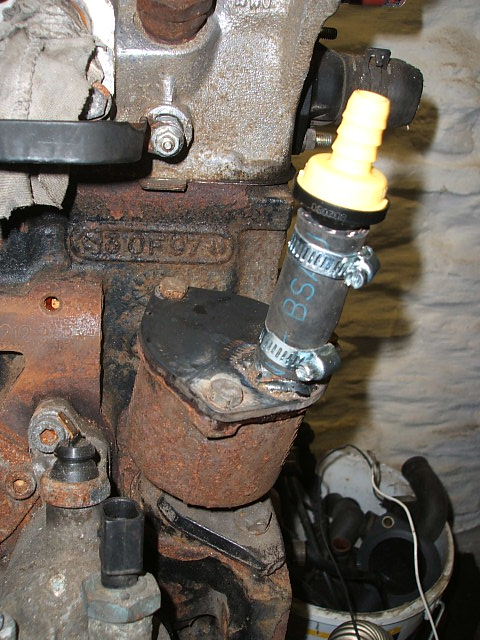
Posted By: colinthefox
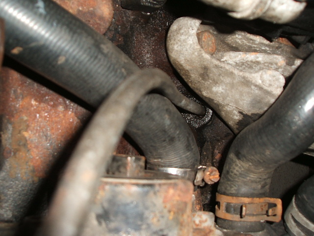
Date Posted: 15 Mar 13 at 11:56
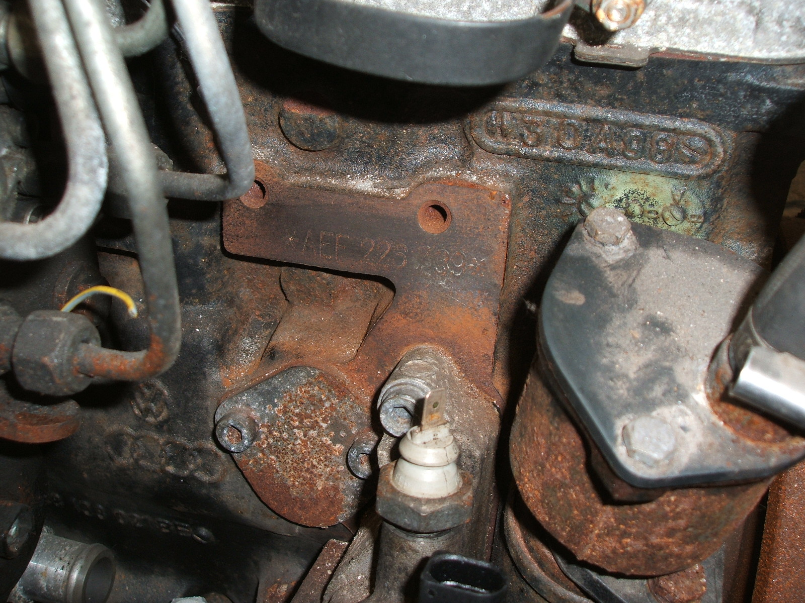 It's helpfully behind the bypass hose. Sandpaper the flat, then wipe with a dirty rag, then a wet finger to reveal the magic number. Better than scratch cards. It's helpfully behind the bypass hose. Sandpaper the flat, then wipe with a dirty rag, then a wet finger to reveal the magic number. Better than scratch cards.------------- 1.9D AEF T3 Kamper All sorts of other oil burners too. |
Posted By: drayton
Date Posted: 28 May 13 at 16:42
| currently on this upgrade, nearly ready to start, one problem the new alternator that came with the aef engine didnt come with plug and wires, I currently have two thick reds and a thin blue, all in a three pin plug that fitted the old alternator, both reds go back to the battery + the blue i presume is the charge light, can any one verify where they go in the picture above there seems to be two lightweight wires going to the plug and socket.. many thanks |
Posted By: colinthefox
Date Posted: 28 May 13 at 17:58
|
You should also have a green wire to your old alternator.
You'll need the alternator plug off a scrapper, (Skoda Felicia 1.9D or VW Polo 1.9D) and make sure you get the wires with it. I think the fat red will come with a lug on each end, one of which goes straight to the +ve of the battery, and the other to the +ve stud on the alternator.
The plug on the alternator has the two thin wires, of which I have found at least two varieties of colours. Anyway whatever colours you have, D+ connects to the blue wire on the van, and W connects to the green wire on the van.
The only real failure I've had with this engine has been the alternator connections, as I didn't make them solidly enough first time, I recommend using the wiring from the AEF and making any joins at the van end where there's less vibration, not using the van wiring and joining at the alternator, where your joints will be shaken to bits. Make sure you get the wiring clamp with the alternator too, this is vital to avoid failures. ------------- 1.9D AEF T3 Kamper All sorts of other oil burners too. |
Posted By: drayton
Date Posted: 28 May 13 at 21:27
| Many thanks, will have a look tomorrow and perhaps visit the local scrappy still waiting for my delay off timer to arrive but should be up and running soon,, excellent write up by the way, would of been lost without it,, cheers ian |
Posted By: drayton
Date Posted: 10 Jun 13 at 11:05
| I dont have a tacho on mine.therefore i dont have the extra wire.. |
Posted By: colinthefox
Date Posted: 11 Jun 13 at 17:37
|
You may not have a tacho, but the green wire is also used for the Buzzer of Doom, and is always there, as far as I'm aware. If you don't have a tacho, and don't need or want a BoD, then you won't need the green wire, and the alternator will function perfectly well without it. ------------- 1.9D AEF T3 Kamper All sorts of other oil burners too. |
Posted By: drayton
Date Posted: 13 Jun 13 at 23:37
| Ok, if its been removed then it must of been cut right back in the sleeve as theres no sign of it.As for the "buzzer of doom" I am guessing that is an audible warning device for no oil pressure (must look that up). and no, not too bothered as i have never had one previously. Anyway replacement alternator going on tomorrow then out for a longer run, been round the lanes a couple of times to try it out and was very impressed, kept it in fourth up the hill and the other half told me to slow down (that was a first)Away next week for a long weekend, over to Coventry to see Springsteen then off to Norfolk,Fingers crossed for weather and faultless trip. Will upload some pics when the forum lets me. |
Posted By: gog
Date Posted: 20 Jul 13 at 17:31
|
Great writeup Colin ! Thanks for taking the time and effort to include such great detail. My T3 was converted from a 1.7D to a 1.9D 1Y engine before I bought it, so now at least I know a lot more of what was involved etc. I also now know why it is so hard to start when the engine is warm, time to go hunting for a 600ohm resistor Thanks again ! Colm. ------------- 1979 LT 35, 1984 cc Petrol Panel Van 1989 T3, 1.9 Diesel (1Y) Tin Top converted panel van |
Posted By: colinthefox
Date Posted: 27 Oct 13 at 19:01
|
Thread resurrection alert!
I have been having a bit of hassle with the Buzzer of Doom" since I did the swap.
The buzzer would chirp as I pulled up at the end of a slip road, or on leaving french roundabouts.
So I fitted an electric oil pressure gauge as a temporary measure to try to find out what was going on. There was definitely an isue with oil frothing, because on the motorway, if the van swayed from side to side, the oil pressure went up and down, but not a worrying amount and this did not happen at lower speeds. That was with the "windage tray" version of the sump gasket fitted. I tried improving the windage tray by blocking holes etc, but that made the variation in oil pressure marginally worse, presumably preventing oil from running freely back into the sump. Then I went back to the standard rubber sump gasket, and raised the level of oil in the sump about 6mm. Much better then, but if I threw the van around I could still get the BoD to chirp.
I hadn't realised the two engines were fitted with different switches,
Sorry for the boring details,
------------- 1.9D AEF T3 Kamper All sorts of other oil burners too. |
Posted By: ThePete
Date Posted: 29 Aug 15 at 12:20
|
Is that fuel pump a Lucas LS4000? Doesn't look like that. I have a LS4000 in my AEF (Skoda Felicia 1,9D 1996 engine) and I am planning to use it with my AEF in T3. But...my pump does not have the immobilizer like yours! I have also a Polo 1,9D 1996 (AEF) and it seems to have the LS4000 too... Trying to figure out the swap for a few weeks and this thread seems to be the very needed help Thank you. Just need to figure out the fuel pump. And I sure don't know anything about those  Any help appreciated... Any help appreciated... |
Posted By: colinthefox
Date Posted: 29 Aug 15 at 18:46
|
Hi ThePete I have no idea whether mine was a Lucas LS4000 or not (1998). I suspect yours is an earlier version if it doesn't have the immobiliser and is 1996. Or it could have a different pump for your country's market. There may be no car theives in Finland! I don't think it mattters which fuel pump your AEF has fitted, as long as it is original to the engine, and has a throttle cable. If the pump is different you will have to figure out the various electrical connections for yourself! It would be a good idea to check the height, just in case it's higher, and would foul the engine lid. Could you post some pictures of your pump so I could have a look? ------------- 1.9D AEF T3 Kamper All sorts of other oil burners too. |
Posted By: Daaf
Date Posted: 02 Feb 16 at 19:15
|
Thank you very much for inspiring me to buy an AEF engine for my T3. Very clear post. I am in the middle of the conversion and have some questions: How do you open the pump for the power steering? I managed to take the iron wire half ring of the back and now I am stuck and can´t open it any further. Anybofy has some more information? Since English is not my first language I don´t understand the part about the thermostat. Do I need to buy a new one, or change the orientation? I am almost done and am very exited to try the engine. Thank you for reading. ------------- Home is where you park |
Posted By: colinthefox
Date Posted: 02 Feb 16 at 21:19
|
Hi Daaf Thanks for your kind comments. You can use the thermostat that came with the AEF. It has a sort of bridge arrangement, and the centre of it holds the pin for the mechanism. The two supports for this bridge should ideally be top and bottom so the coolant has minimum resistance to flowing horizontally. Is that what's confusing you? I don't think it's all that important really. As for the power steering pump, mine could be different because it came off a Skoda of some description. Anyway, I can't really remember the details of stripping it down, as it was a few years ago. Sorry I can't help. Best of luck with your new engine. ------------- 1.9D AEF T3 Kamper All sorts of other oil burners too. |
Posted By: melront
Date Posted: 18 Feb 16 at 16:00
|
This will be my plan for spring :) I've just bought new (old) engine. Thank you very much for this how to :) My 1.6D was really slow in hills (moving up :) |
Posted By: colinthefox
Date Posted: 18 Feb 16 at 20:51
|
You should have plenty of Skoda Felicias to choose from where you are! ------------- 1.9D AEF T3 Kamper All sorts of other oil burners too. |
Posted By: melront
Date Posted: 23 Feb 16 at 09:42
|
Actually engine is from VW Polo, but it should be the same. But the main problem is lack of experience in my case :) |
Posted By: Daaf
Date Posted: 07 May 16 at 15:15
|
Hello Everybody, I swapped my 1.6D to an AEF and I am still in the process of fine tuning. I bought an engine at a scrapyard in Spain, it looked very clean and it had made in Mexico written on it. Never saw that before... I found it very difficult to drill the hole for the dipstick, I mean to get the right angle. Ended up hitting the engine mount hole as well... When I had the dipstick in it blew out a lot of oil when the engine was running. Had to take of the dipstick tube that was under the oil level and solved that. I made a switch on the dashboard for the "commencement of injection" solenoid of the dieselpump. I found out that I can only put the switch in the off position after the engine is completely warmed up. If I do it earlier the engine sputters at low refs and gives some white smoke. I am thinking that maybe the timing of the diesel pump is a bit off. I put the timing belt on with the CS flywheel and T3 gearbox TDC mark. I hope that is the right way. I am a bit disappointed in the fuel consumption it is almost 10 liters for 100 km. My 4 speed gearbox is also not helping for a good consumption. I also couldn't open the pump for the steering assistance, it was a model that couldn't be opened so i took the internal parts out and closed it with some oil inside. Lately I had a lot of coolant leaks, there is a lot of pressure on the hoses. I ordered a new expansion tank cover to see if that helps. Also notice a contact sound when i drive backwards, I think it is the exhaust pipe hitting something. Well, it was a nice project and I am thinking of buying a space AEF in case of trouble. Maybe not a "made in mexico" this time. Is there somebody who also have the same experience with the "commencement of injection" solenoid switch timing? Keep up the good work :) ------------- Home is where you park |
Posted By: colinthefox
Date Posted: 17 May 16 at 22:06
|
Sorry, missed your post. I didn't get an email notification. Yes it does sound like the timing is not right. Apart from recommending the usual checks I can't help you with that. The pressurisation of the cooling system doesn't look good though. Could be cracked cylinder head or blown head gasket I suppose. You could get the coolant tested at a garage. The commencement of injection solenoid should work as I described. Your problems could be due to the timing or connected to the cooling system problems. To be honest I would suspect that your engine is bad, but can't be sure based on what you have said. ------------- 1.9D AEF T3 Kamper All sorts of other oil burners too. |
Posted By: Daaf
Date Posted: 15 Jul 16 at 22:44
|
thank you for the reply. a little update after some months of daily driving. The problems with the pressurised cooling system is solved with a new pressure cap. The engine is getting considerable warmer than the CS engine but I didn't have a boiling engine yet. I live in Spain though in a mountain area so I am always keeping an eye on the temperature gauge. The bearings of the powersteering pump broke because lack of oil. I bought an other one that I could open and now I keep an eye on the level in the pump every 1000km. I have a friend with a broken JX engine and I told her that the cheapest fix will be to replace it with an AEF. so maybe I will do a JX to AEF conversion soon. Almost forgot to tell that I bought an other gearbox and now I am able to drive 110 km/hour and I use 8 liters for 100km. Hope to read some more folow ups about the AEF. Thank for the very useful information [:)] ------------- Home is where you park |
Posted By: colinthefox
Date Posted: 17 Jul 16 at 21:06
|
Daaf Glad you got it sorted, and thank you for posting feedback. It really does help others. We drove over the Picos twice last year, and really enjoyed the trip. Twelve years ago we did that with the CS engine and really struggled! Colin ------------- 1.9D AEF T3 Kamper All sorts of other oil burners too. |
Posted By: whizwest
Date Posted: 25 Aug 16 at 10:16
|
Hi Colin, some time ago you posted an excellent article about exchanging a 1.6 to the 1.9D AEF engine. I have done the refit and it's running, but I have a problem. It idle's ok on tickover , and then when you drive it, it accelerates ok, then went you take your foot off the gas, it stalls. your article talks about the high idle vacuum activator, and the air bleed screw? Any advice? Thanks Chris (whizwest) |
Posted By: colinthefox
Date Posted: 25 Aug 16 at 15:33
|
Chris. Once the diesel system has been filled and the engine running, the air bleed screw does nothing. The high idle device has very little effect on anything really. Just as it's name suggests, it varies the idle speed a bit, but shouldn't lead to stalling either way. I don't really have any idea about your stalling problem, except to check that you don't have an air leak on the suction side of the pump, and that the idle screw hasn't been interfered with. Good luck Colin ------------- 1.9D AEF T3 Kamper All sorts of other oil burners too. |
Posted By: fdb
Date Posted: 13 Sep 16 at 14:06
|
Hi looking for some help please. Fitted a aef engine from a skoda fabia 1.9. Got her running but if I over rev she cuts out and the timings are then out so won't restart without putting the timings right, anyone got any help to offer please. Thanks |
Posted By: colinthefox
Date Posted: 13 Sep 16 at 20:56
|
Sorry, once again I don't hve much clue as to what might be wrong, except to look at the fitting of the timing belt and in particular the tensioner. Is the belt running true? ------------- 1.9D AEF T3 Kamper All sorts of other oil burners too. |
Posted By: boatbuilder
Date Posted: 15 Jan 17 at 00:13
|
Thanks for the brilliant guide. I'm working through it at the moment so I may have some questions! Does it cause any issues having the delay off switch operating even on an already hot engine? |
Posted By: colinthefox
Date Posted: 15 Jan 17 at 21:40
Good question. No. It just advances the injection a bit, making it sound a bit more dieselly. Best of luck with the conversion. ------------- 1.9D AEF T3 Kamper All sorts of other oil burners too. |
Posted By: boatbuilder
Date Posted: 16 Jan 17 at 00:34
| Thanks for that. Getting there slowly. Just removed the vanes from the power steering pump today...don't have any power steering fluid handy and would rather not have to buy a bottle to fill up the tiny pump. Do you think I could use any other kind of oil in there instead? I'm planning to plug the bottom outlet of the pump with jb weld and a coin and just plug the middle of the top outlet so it can still be unscrewed if needed. |
Posted By: colinthefox
Date Posted: 16 Jan 17 at 09:39
|
Engine oil is perfectly OK. Once you've removed the vanes it's just an idler wheel. It's up to you how you blank off the ports, but I like to have a mechanical retention in addition to adhesive in case of failure. ------------- 1.9D AEF T3 Kamper All sorts of other oil burners too. |
Posted By: Antzg
Date Posted: 20 Jan 17 at 11:30
|
What a fantastic guide! this has saved me so much time so many thanks for your hard work! I bought my van with the engine already removed so have a little dilemma. I just wondered if any of you lovely people could tell be which colour wires go to where? currently I have the following: Black - ignition live for fuel stop solenoid Blue/white - to heater plug temp switch blue/black - to oil pressure switch on the head??? red - glow plug I currently have the remaining: black yellow yellow/red Thanks you in advance :) |
Posted By: boatbuilder
Date Posted: 06 Feb 17 at 18:00
|
Lots of wiring questions at the minute! The AEF alternator has three connections - not sure where to connect them all up: B+ main heavy wire to + battery terminal D+ blue wire to the dash charging led W not sure what this is for? - never mind, I've figured it out, its for a Rev counter if you have one. |
Posted By: boatbuilder
Date Posted: 09 Feb 17 at 09:01
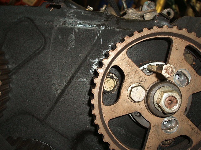
| Does the AEF suffer from the crank bolt problems like the AAZ does? Just wondering if I should undo the crank bolt and torque up a new one? Or just leave the old one untouched? |
Posted By: mrhutch
Date Posted: 09 Feb 17 at 14:30
|
not as much as the turbo but I often do change them anyway, especially if there doing a t-belt/waterpump anyway ------------- T3 1981 Westy Vanagon - thinks lubricant is a fuel |
Posted By: boatbuilder
Date Posted: 10 Feb 17 at 17:46
|
So I've bought this little delay off relay. It's really tiny, not sure where to put it. Can't make sense of the wiring on it. Can anyone help with what to connect up where ?  |
Posted By: boatbuilder
Date Posted: 13 Feb 17 at 11:39
|
So I think I've figured it out... It doesn't seem to be possible to wire this in with the starter wire because once the engine is started, the starter wire goes back to zero volts which makes the relay switch off instantly, which is obviously no good. I'm going to connect it to the ignition wire instead. The only issue I can see is that you'd have to make allowances for the length of glow time as the relay starts counting down from the second you turn on the ignition. So I'm guessing I'll probably set the relay for the maximum time of 40 seconds.  |
Posted By: colinthefox
Date Posted: 22 Feb 17 at 13:17
Sorry, missed these last few, as I've been away for a couple of weeks in a place with no internet or mobile phone. Bliss! (No, not prison. We know they all have mobiles there!) No. The AEF shouldn't suffer from the crank bolt problem, as the alternator should have a clutched pulley, and the belt won't be putting rotational stress on the crank pulley. If it's OK now I would leave it. I think you've sussed out the relay wiring. It's actually not the relay I would have chosen, as doesn't have a separate trigger wire, but it will do OK the way you've got it. It would be great to get feedback once you have it running. ------------- 1.9D AEF T3 Kamper All sorts of other oil burners too. |
Posted By: boatbuilder
Date Posted: 25 Feb 17 at 22:24
|
It seems to be working well. Not a hint of smoke at start up. I've noticed that after the glow plug light goes out, the plug relay stays active for another few seconds and then you hear it clicking off. I presume this is something to do with the resistors on the glow plug wire. I had thought it would have been in sync with the light? So far so good, looks like the gamble on the 100 quid engine paid off... I had to rebuild the alternator as it was very noisy and I'm chasing various coolant hose leaks and my gearbox or clutch is rattling at idle unless you press the clutch pedal.... The AEF itself is a lot more smooth than the old CS and as someone already said, you can generally go up hills in a gear higher than before. I'm thinking a sensible cruisng speed would be 55mph..... what does everyone else do? Oh and I have no oil leaks! Proud of that one! |
Posted By: colinthefox
Date Posted: 25 Feb 17 at 23:37
Well done. I bet you were grinning from ear to ear by the time you got into third!
I think it's designed for a bit of "Afterglow". Nothing to do with the resistor. Well done for no leaks. I had no leaks initially, but have just had to pull the gearbox 20K miles on because the rear crank seal was leaking. 55mph is about right for cruising with the standard gearbox. You could always slip in a longer top gear set. I think they are 0.77. That would retain the hill climbing of 3 gears, with cruising at 60. The clutch rattle is probably the drive springs on your clutch plate a bit loose. To diagnose that, if you let the clutch out veeeeeeery slowly in neutral, it probably won't do it. Not a problem. Now grab yourself a 100 quid spare engine, to be sure. Incidentally, my clutch plate that has done 20K miles still has the numbers printed on the wearing face. You can pull away at an idle in most situations. ------------- 1.9D AEF T3 Kamper All sorts of other oil burners too. |
Posted By: rowlesy
Date Posted: 30 Jul 17 at 22:06
|
just thought i'd put this up here.... my aef's been in for possibly three months now and ive always had a rattle not long after fitting sometimes at tick over sometimes at full chat and sometimes all the time even with clutch depressed! i read somewhere that the newer engines vibrate a bit in the t3 because there now not harmonized along with there old gearbox and engine mounts? i thought that was kindof bollox as ive put a fair few un-t3 engines in these buses! so i was having difficulty locating the noise i thought the worse and whipped off sump to check crank and con rods. all fine there..... so took of upper and lower cambelt covers off to have a mooch there. again looked fine but lots of metal filings? so a bit more messing turned up a spacer that had dropped down behind the oil pump pulley and was sat there rattling around! once i got that out i figured out where it had come from......to take the engine out the caddy (skoda) one of the engine mounts is just below the crankshaft pulley. when i took this off unbeknown to me theres a spacer that sits under that mount. it must of dropped out when i undid the bolts! so there you go just a heads up! i did think the engine was fucked hence taking the sump back off! ------------- UberFukz broke another! sucky sucky five dollah! always out numbered never out gunned! RWS welding 07846 380 467 (worcs) |
Posted By: colinthefox
Date Posted: 30 Jul 17 at 22:42
|
Oooh! Lucky it didn't jam the oil pump pulley then. That would have been terminal! ------------- 1.9D AEF T3 Kamper All sorts of other oil burners too. |
Posted By: rowlesy
Date Posted: 31 Jul 17 at 10:46
|
oh yes made me tut i can tell you! i really thought it was main bearings or clutch problems.... ------------- UberFukz broke another! sucky sucky five dollah! always out numbered never out gunned! RWS welding 07846 380 467 (worcs) |
Posted By: skipperdiego
Date Posted: 31 Mar 20 at 14:05
| I'm waiting the AEF to arrive from the scrapeyard, I hope it's a no-ECU version |
Posted By: mrhutch
Date Posted: 31 Mar 20 at 21:51
|
they are all non-ecu (kind of) some do have immob though ------------- T3 1981 Westy Vanagon - thinks lubricant is a fuel |
Posted By: skipperdiego
Date Posted: 01 Apr 20 at 00:23
|
I think it has immobilizer on injection pump |
Posted By: mrhutch
Date Posted: 01 Apr 20 at 00:53
|
That’s easily done. Post a photo of what you have.
------------- T3 1981 Westy Vanagon - thinks lubricant is a fuel |
Posted By: roonster
Date Posted: 19 Dec 20 at 15:28
| great write up this just installed an aef into our van but it's originally a petrol so I need to sort out wiring? Don't know if different |
Posted By: colinthefox
Date Posted: 20 Dec 20 at 20:15
There will be a load of differences between the old Petrol wiring and the AEF. You'll need glow plug wiring and relay, and a light on the dash. If you have a tacho, that will operate differently, taking its signal from the W terminal on the alternator, as does the buzzer of doom. I can't really help with that as I've never converted from petrol to diesel, but others have, and may be able to help. ------------- 1.9D AEF T3 Kamper All sorts of other oil burners too. |
Posted By: colinthefox
Date Posted: 20 Dec 20 at 21:09
|
...........Oh, and of course the battery will need to be bigger. Diesel batteries are normally in the engine compartment. If leaving the battery in the front of the van, the size of the main cable to the starter motor will have to be increased substantially, and I'm not sure you can get a diesel starter battery shallow enough to fit under the seat. ------------- 1.9D AEF T3 Kamper All sorts of other oil burners too. |
Posted By: roonster
Date Posted: 02 Mar 21 at 17:03
|
colin you were correct the battery I have is rather big for the diesel won't fit under seat so will move it to enige Bay, only managed to get this fores up briefly other day after waiting nearly a year lol It fire so that a bonus still need to sort out wiring and exhaust but slowly does it lol sounded good tho ANY pointers with wiring guys would be appreciated as I say petrol to iesel conversion
|
Posted By: colinthefox
Date Posted: 02 Mar 21 at 22:49
Well done for getting it running.  Sorry, I can't help you any more with the wiring. Sorry, I can't help you any more with the wiring. ------------- 1.9D AEF T3 Kamper All sorts of other oil burners too. |
Posted By: roonster
Date Posted: 15 Jun 21 at 06:07
|
van past mot running fine then it all went shit !!! Started to splutter and stutter s bit like lack of fuel ? Found a little leak so hopefully just that
|