

|
|
1984 1.9DG to AGG Conversion |
Post Reply 
|
Page 123 4> |
| Author | |
club joker 84 
Groupie 
Joined: 21 Jul 09 Location: Cornwall Status: Offline Points: 138 |
 Post Options Post Options
") Thanks(0) Thanks(0)
 Quote Reply Quote Reply
 Topic: 1984 1.9DG to AGG Conversion Topic: 1984 1.9DG to AGG ConversionPosted: 31 Oct 16 at 00:10 |
|
Thought I would share with you the long-running saga of my
AGG engine conversion. Thanks have to go
to GaryD for sharing his ‘bible’.
Certainly wouldn’t have got to this stage without it! I am reasonably mechanically competent and
usually do own servicing etc., but I am no mechanic and this is the most
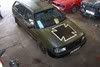
complicated thing I have attempted. My van is a 1984 Westfalia Club Joker, originally a 1.9DG on
a DU gearbox. About 2 years ago it
started losing water. Held it at bay for
about a year using Wynns Radiator Stop Leak.
I am not usually one for magic potions, but this is impressive
stuff! Worked surprisingly well, but
eventually the water jacket seals were too much for it and I had to take the van
off the road. I had been thinking about
an AGG conversion for a while, and this seemed like the time to do it. I had previously stockpiled most of the JX bits needed for
the conversion: -
Sump -
Mounts -
Engine bars (including the plates welded into
the van). I think mine are the early bars -
Bell housing -
Exhaust back box -
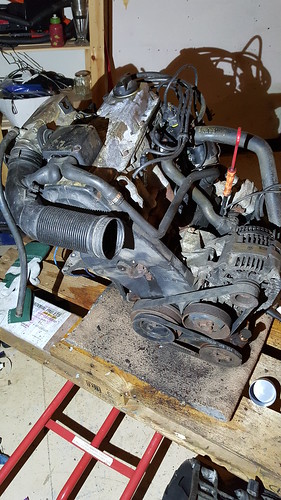
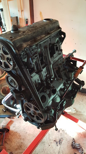
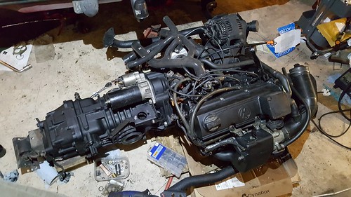
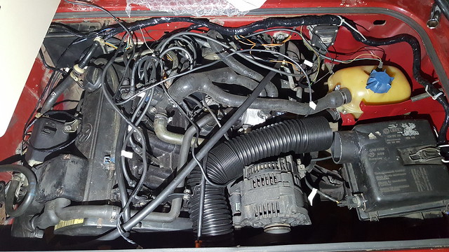
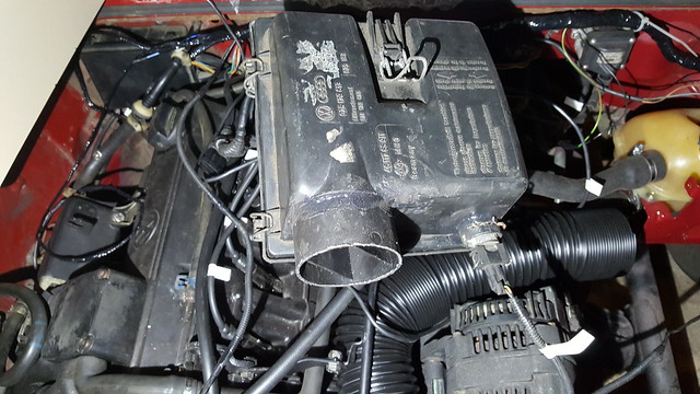
Oil pump, dipstick, filler neck Took a chance and managed to get and AGG engine + loom + ecu
+ immobiliser + MAF, etc. from ebay for £100. Was a non-aircon model, which was result as it
has the right alternator and stand from the start. This is what it looked like on arrival – bit grubby,
but no signs of any leaks etc.:
Dropped the original engine and gearbox out of the van and
onto a pallet using a couple of jacks. Lifted
the van as high as I could get it on axle stands and dragged engine and box out
from underneath. Split the box from the
engine
Brought a cheapie engine stand off e-bay (£34
delivered!). Using a jack and a great
deal of swearing, I managed to fix the GTI engine to it after taking off the Golf
clutch and flywheel. (Top tip – if you
have an engine on a pallet balanced on to of a trolley jack and partly bolted
to your engine stand, make sure that the other bolts you need are within
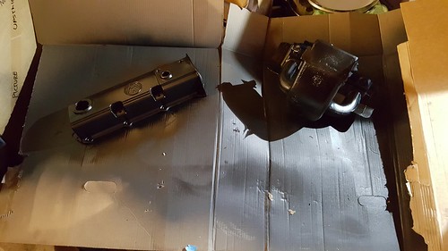
reach!). Took all of the ancillaries off the GTI engine, labelling as
I went and putting them in boxes.
Cleaned it up using Gunk, hot water and small brushes, followed by the
cheap soap filled scouring pads you get in the supermarket and finally with
thinners. Any really grubby bits got a
going over with a wire brush on a cheapie drill from screwfix. Wanted it to look nice, so painted it with
high temp paint - Plasti-Kote Black Satin BBQ Paint. Seems like good stuff. Stays a bit soft until it’s got hot, but
looks really good. Time will tell how it
stands up to oil, etc.
Any bits that were
small enough got the same treatment, and were then put in the dildo oven at
full temperature (waited until my wife went out!). This included the manifolds, sump, etc.
Mounts, etc. got the same again, but Halfords Truck Bed liner. Again, time will tell how it lasts. Before painting, the mounts were cleaned with
a wire brush and drill. They had quite a
lot of surface rust, so took a chance on cleaning them up using citric
acid. Got a 5kg bag of it from e-bay.
Mixed it up with hot water in a storage box and soaked them overnight. The results were really impressive, so
everything else that was rusty got dipped and sprayed from then on! Didn’t take any pictures of this for some
reason, but it was good. Went for a coat
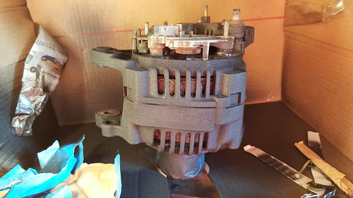
of etch primer (UPOL) before the truck bed liner. Alternator was also cleaned and painted. Took the obvious bits off first, but didn’t
go mad. Slipped bits of cardboard into the
cooling bits to mask off the copper windings.
Came out nice.
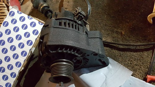
You may have noticed that I managed to get an allen key
stuck in my alternator pulley bolt. It’s
still there. I can’t get it out, no
matter what I try. I think I’ll just
live with it! I was getting a bit anal about the whole thing now, so splashed
out in stainless bolts. I went for these
ones from Liquid Metal Refinement.
Not an exact match for the AGG, but not far off. Came clearly labelled etc. so was happy with
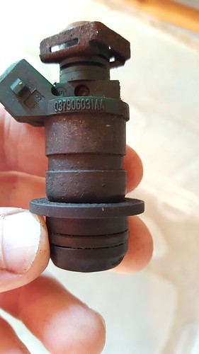
them. Injectors looked a bit manky:
Decided to rebuild them.
Used this
kit from Mr Injector UK. Quite easy
to do. Used plenty of injector cleaner. Got new water pump, cambelt, oil filter, plugs, leads, rotor
arm, dizzy cap, thermostat, gaskets, etc. from GSF. Also picked up a second hand starter and JX
header tank bracket. From Brickwerks I
got clutch pilot bearing, thermostat housing, flywheel bolts, fuel pump and
filter, a 2.1 fuel supply hose kit and bulkhead pipe fitting, bell housing bolts
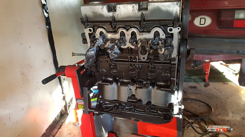
and silicon JX cooling hoses. Built the engine
up on the stand as per GaryD’s instructions.
I did manage to retain the heat shield around the exhaust manifold by
cutting bits away with tin snips until it fitted. I had to fabricate a little bracket to hold the dipstick in the
right place. Used the old clutch slave
bracket support. This bolted up to the lifting eye.
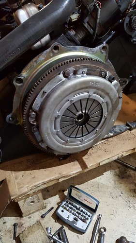
Put engine back on pallet (more swearing) and fitted clutch
and flywheel.
Edited by club joker 84 - 31 Oct 16 at 00:14 |
|
 |
|
|
club joker 84
Groupie
Joined: 21 Jul 09 Location: Cornwall Status: Offline Points: 138 |
Post Options
Thanks(0)
Quote Reply
Posted: 31 Oct 16 at 00:13 |
|
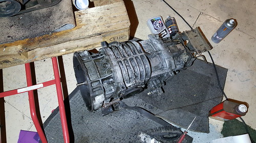
Time to sort out gearbox.
Gave it a good clean up using allow wheel cleaner, scouring
pads and wire brush. Took bloody
ages. Drained oil and stood it up on its
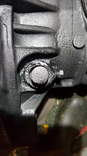
end and removed the bell housing. After
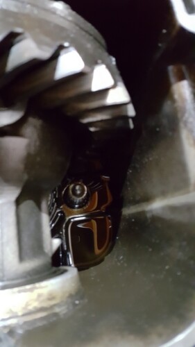
a lot of head scratching I managed to remove the input shaft. There is a sleeve that fits over the end
facing into the gearbox. This has
splines that stop it unscrewing. You
just lift this up and out of the way (easier said than done!) and unscrew. You can just about see the place where it
screws into in this picture.
I didn’t have a diesel one to swap it for, so I carefully
cut it down using a hacksaw and filed a chamfer on it. That stuff is seriously hard! Refitted it and diesel bell housing with new gasket and
bolts. It all then had another clean up
and a spray with etch primer and truck be liner. It was at this stage that I noticed that the
clutch cross shaft was quite loose in the bellhousing. Also,
the splines on the end the circlip groove were quite knackered, so I decided to
swap it for the one from the petrol bell housing.
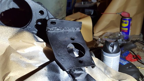
Had to cut the clutch arm off both of them in the end! It looks like the diesel clutch slave bracket
had sheared off its mount to the starter bolt and been slopping around for a
while and worn away this area of the bellhousing. Wasn’t about to splash out on another bell
housing, so decided to beef up the way that the clutch bracket mounts. First I welded an additional plate onto it to
repair the mount to the starter bolt.
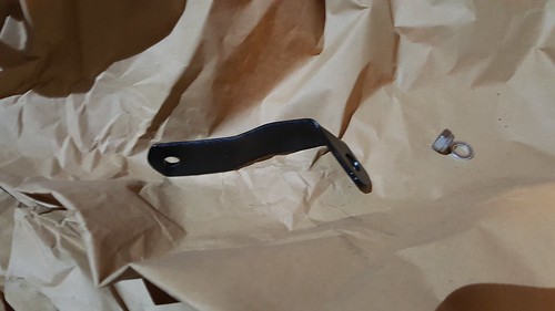
Then I bent up another bracket that would mount to another
of the engine bolts.
I also filled in the worn bit of bell housing with chemical
metal and assembled it all, with new bushes.
All seems very solid, so happy with it.
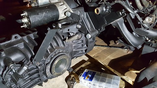
Then it was all bolted up to the engine with starter etc,
and new hoses. These were a bit of a
head scratcher as I didn’t have any references.
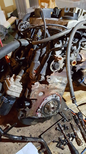
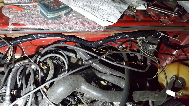
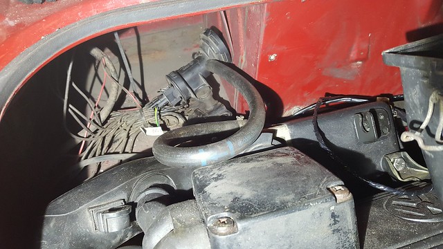
After plenty of Google image searching I worked it out. The main tricky bits to work out were the
link between the water pump, the flange on the head and the oil cooler. In the Golf they are all linked with one
hose. In the T3, the oil pump isn’t
connected to this hose, but to one of the main hoses. I used the original Golf hose and put a bung
in the hole that used to connect to the oil cooler. Another one is where the extra, electric
coolant pump usually goes. This is
apparently not needed for the AGG, so you just join these two bits
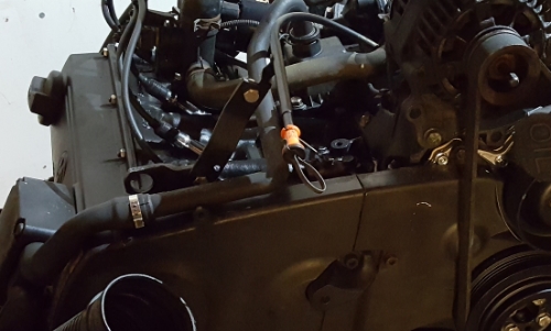
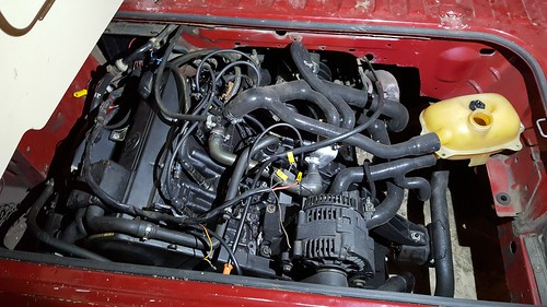
together. Lastly, the two water pipes
from the throttle body. I connected on
to the manifold on the side of the head (kept the Golf one and there was an
inlet of the right size on it). Just
blocked the other one up. Not sure if this
is right or wrong. Hopefully you can see
them in this picture.
Got it mounted in the van using my patented pallet, jack and
swearing method.
Set to on the wiring, followed GaryD’s notes on this. Daunting as it seems at first, it is quite
straightforward and you cut out most of it.
Just follow everything from the ECU connector and keep it. Remove everything else I think. Plugged it all in.
Added a multicore cable to the front for speed sensor, immobiliser, etc. Mounted immobiliser and OBD socket behind
dash. Fired it up, but it wouldn’t run
for more than a few seconds. Had an
immobiliser-related error code, so cleared that. Moved a few earths around and tried
again. It held on a bit longer. Had an error code relating to the hall
sender, so reset distributor timing and it runs! Anyway, that’s where I am up to with it. Thought I would share whilst I finish it
off. Don’t expect quick progress, I grab
a few hours when I can! |
|
|
|
|
Bromy
Vanorak 
Joined: 26 Feb 12 Location: Cambridge Status: Offline Points: 1303 |
Post Options
Thanks(0)
Quote Reply
Posted: 31 Oct 16 at 00:42 |
|
Nice one, looking good

|
|
|
"follow the masses, do the opposite"
|
|
|
|
|
fufflenarnia
Vanorak

#1 Cable Shift Bitch Joined: 04 Sep 10 Location: Redhill, Surrey Status: Offline Points: 1362 |
Post Options
Thanks(0)
Quote Reply
Posted: 31 Oct 16 at 18:18 |
|
Good work, it's a cracking conversion
|
|
|
|
|
club joker 84
Groupie
Joined: 21 Jul 09 Location: Cornwall Status: Offline Points: 138 |
Post Options
Thanks(0)
Quote Reply
Posted: 16 Nov 16 at 22:37 |
|
Bit if an update.
Managed to get a few hours on the van the other day.
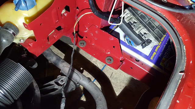
As mine started life as petrol, my battery is under the
passenger seat, leaving me with a big space in the back right hand corner of
the engine bay. The plan is to mount the
ecu behind the offside rear light, with the airbox in front of it. First job was to flatten out the ECU mount so that I can
bolt it all up easily. Just did this in
a vice. Will get some plastic bolts and
stick on feet so that I can mount this and keep it insulated from the chassis.
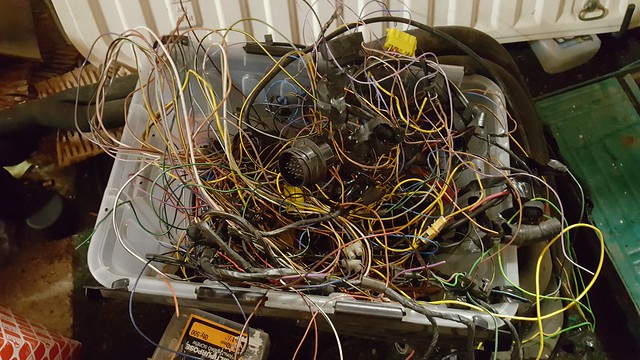
Next job was to shorten the loom so that it fitted well
around the front of the engine bay. This
was pretty tedious, and involved cutting about 14 inches out of each wire,
stripping the ends back and soldering them together. Each one was then covered with
heatshrink. I tried to stagger the cut
points so that I wouldn’t end up with a bulge where all the joins were. By the time you have done about 35 of these
it gets quite boring! No pictures of
this bit. Here's a picture of all the crap that was cut out from the whole loom:
Next job was to wrap the loom. I used non adhesive loom tape for this. I used black insulation tape to tape the loom up every 4 inches or so, with extra tape around any branches to prevent it being pulled out of shape. I then wrapped it all up in the loom tape. This was easy to do, but quite time consuming.
Also managed to get all of the relays, fuses, etc. tucked away in the original wiring box in the engine bay. It is absolutely packed in there, but the lid does just about go on.
The plan is to
fix the loom in place using cable ties and mounting blocks – a job for another
day.
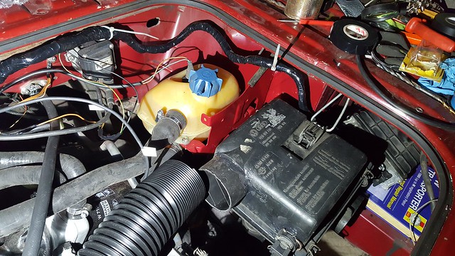
Charcoal canister valve thing will go behind the nearside
light, nice and close to the throttle body, so that the hose can be connected
up as per the GTI. Don’t think this is
really necessary tbh. Loosely in place here:
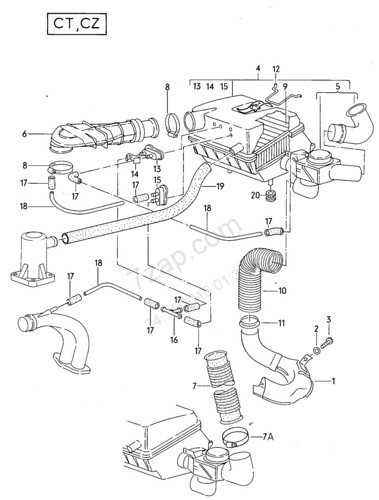
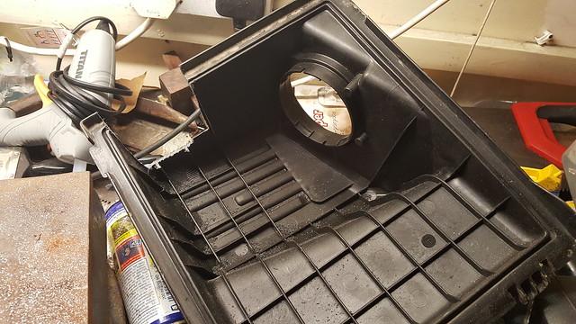
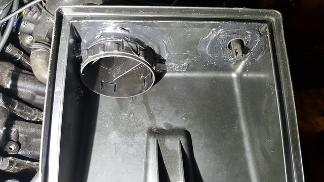
The other job I tackled was the airbox. I wanted to try to use a full airbox if
possible just to keep it a bit quieter and more factory looking. I had the original square DG box, and the GTI
one. The GTI one is a fair bit bigger
and has a larger outlet and also a fixture for the inlet temperature sensor. The intake to the box seems to be smaller if
anything. I couldn’t find a good way of tucking the GTI box under the
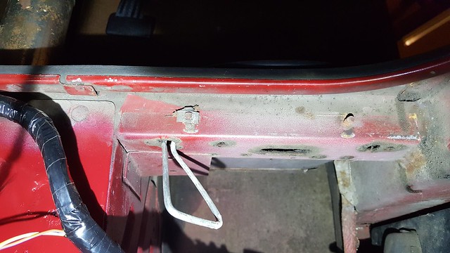
engine lid, so I started to think how I could use the DG box. The smaller outlet and lack of a sensor mount
were a problem. I had the original mount
that I had removed to make way for the coolant tank. After a bit of measuring out and a couple of
trial runs, I found that I could weld it to the chassis rail, allowing the
airbox to be mounted.
I needed to find a way of clipping it in place. The original clip just attaches to a loop of
stiff wire. I couldn’t see a way to get
this out to reuse it unfortunately.
However, I think it would have been too short, as the airbox is lower
than it was originally. I looked around my
workshop for something I could use. I found a bucket with a strong wire handle,
so cut it off. I made up a dummy one
from some soft garden wire, and then bent the bucket handle to match. Fortunately there is already a hole in the
bottom of the engine bay cross member just in the right place, so I used this
to mount the wire. I just bent the ends
at right angles, cut them quite short and put them up through the hole. The spring tension of the wire holds it in
place.
The box clips in place really nicely, so I was pleased with
that
The outlet from the GTI box is a separate piece that kind of
screws into the main box. It’s got a lip
on it, so I thought it might be possible to cut out the original DG outlet,
enlarge the hole and put the GTI outlet through from the back and glue it in
place. A bit of careful marking and
using a dremel soon had the hole big enough.
I just took it slow and kept trying it for size. I did the same thing for the inlet temperature sensor mount. I cut it out of the GTI box, with a section of box around the mount.
Cut a new hole in the DG box and put the GTI sensor mount through from the back. These were then fixed in place using black silicon sealant / panel adhesive stuff.
Came out quite neat in the end:
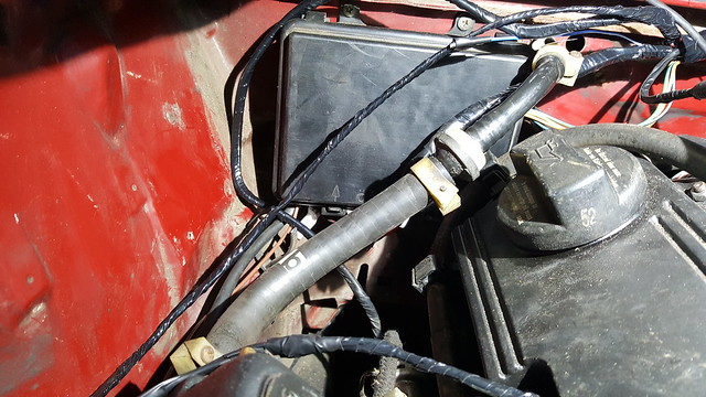
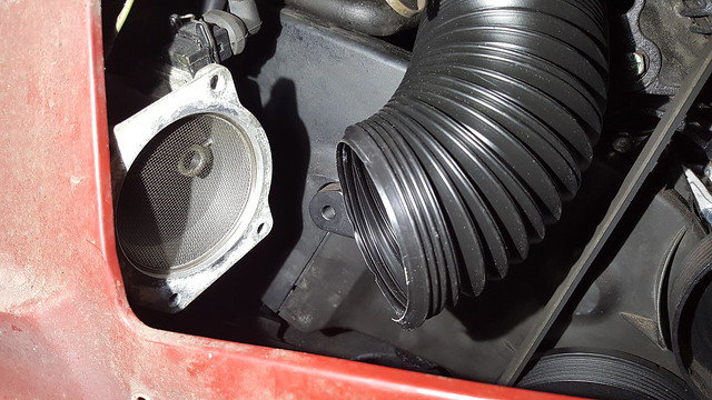
I have a length of Flexi Duct http://www.autosiliconehoses.com/silicone-hose-shop/air-ductings/pvc-plastic-air-ducting.html. Plan is to run this around the back of the alternator,
under the dipstick and onto the MAF.
Loosely in place in this picture. 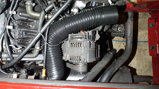 I plan to make up a bracket to hold the MAF in place using the blind bolt hole from the front of the GTI engine (not sure what this is supposed to be for). This will be one of the next jobs…
More to follow when I get a bit more time on it. |
|
|
|
|
rowlesy
Vanorak
murdered the murderwagen Joined: 09 Oct 05 Location: up unit! Status: Offline Points: 6466 |
Post Options
Thanks(0)
Quote Reply
Posted: 17 Nov 16 at 21:09 |
|
looking good and some nice solutions for the airbox
|
|
|
UberFukz broke another! sucky sucky five dollah!
always out numbered never out gunned! RWS welding 07846 380 467 (worcs) |
|
|
|
|
booted
Vanorak

Joined: 13 May 07 Location: Luton Status: Offline Points: 2671 |
Post Options
Thanks(0)
Quote Reply
Posted: 23 Nov 16 at 11:04 |
|
My dg airbox is nothing like your one is there a part number on it ?

|
|
|
|
|
Bromy
Vanorak
Joined: 26 Feb 12 Location: Cambridge Status: Offline Points: 1303 |
Post Options
Thanks(0)
Quote Reply
Posted: 23 Nov 16 at 13:18 |
|
His is from the donor isnt it?
|
|
|
"follow the masses, do the opposite"
|
|
|
|
|
booted
Vanorak
Joined: 13 May 07 Location: Luton Status: Offline Points: 2671 |
Post Options
Thanks(0)
Quote Reply
Posted: 23 Nov 16 at 13:50 |
|
I thought you cut up the donor one and fitted the bits to tha square one in the photo
Edited by booted - 23 Nov 16 at 13:51 |
|
|
|
|
Bromy
Vanorak
Joined: 26 Feb 12 Location: Cambridge Status: Offline Points: 1303 |
Post Options
Thanks(0)
Quote Reply
Posted: 23 Nov 16 at 17:10 |
|
Yeah i think your right actually

|
|
|
"follow the masses, do the opposite"
|
|
|
|
|
club joker 84
Groupie
Joined: 21 Jul 09 Location: Cornwall Status: Offline Points: 138 |
Post Options
Thanks(0)
Quote Reply
Posted: 23 Nov 16 at 22:53 |
|
My original DG airbox is / was square, like this one:
 I think that this is the early version. If you click on my photos of it you should see a huge version where you can see the part numbers. I grafted the Golf outlet and air temp sensor into this. The Golf box is also square-ish. Not sure if you would be able to do this with the round version. This guy has found a nice neat way to use the Golf box though.
|
|
|
|
|
Titus A Duxass
Vanorak
Joined: 12 Feb 08 Location: Lossatal, Germ. Status: Offline Points: 2164 |
Post Options
Thanks(0)
Quote Reply
Posted: 24 Nov 16 at 16:11 |
That's very similar set up that I've done using a Hyundai Getz air box. |
|
|
Bollocks to it all!!
51°24′N 12°52′E |
|
|
|
|
club joker 84
Groupie
Joined: 21 Jul 09 Location: Cornwall Status: Offline Points: 138 |
Post Options
Thanks(0)
Quote Reply
Posted: 07 Dec 16 at 23:21 |
|
More progress on the air intake. Firstly I had to modify the airbox I had made a bit because the hose that I had bought didn't quite fit over the outlet. I had to slot in something just a bit smaller. After rooting through bits and bobs in my workshop, I found just the right thing. Of all things it was one of those small cans of baked beans!
To get it in there, I cut the outlet short, user a Dremel to cut down the air guides inside a bit and slotted it in and used the same mastic stuff to glue it in place. Once it was all dried I gave it a blow over with etch primer and matt black paint. 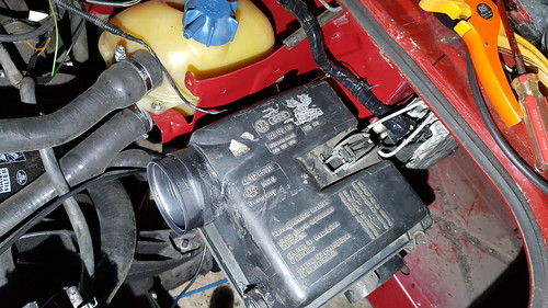 Next step was to make up a bracket for the MAF. This was done from a little strip of steel that I had hanging around. I made a card template first and then copied it. Nothing complicated, just bent using a vice and cut and filed to shape.  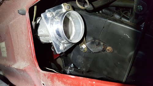 The bracket just bolts up to the MAF adapter and to the blind tapped hole on the front of the engine block. Then I got the air hose on: 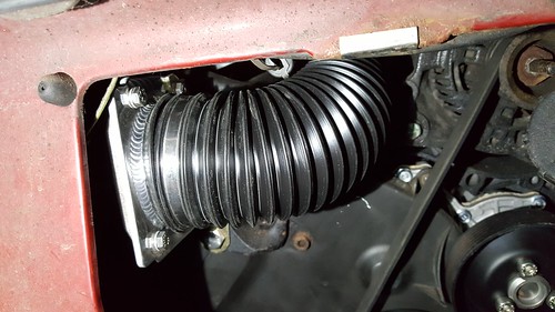 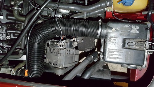 Also got the ECU mounted. This went behind the right rear light. I use the original mounting plate, but drilled some extra holes and used plastic nuts and bolts to isolate it from the body. 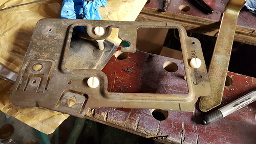 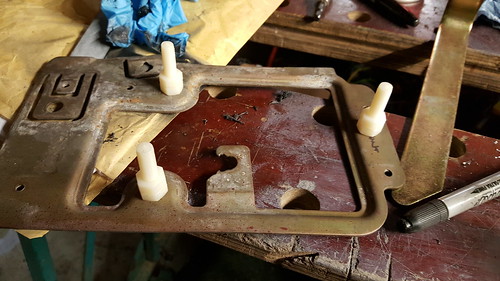 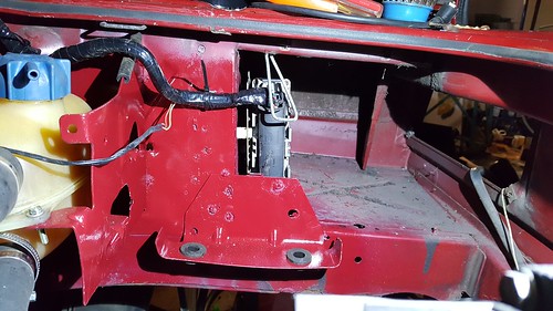 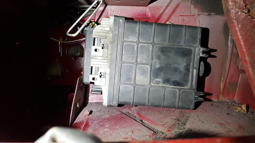 Next step, exhaust. I have used an old wire coathanger to bend to shape and measure, and ordered some bits and pieces from Profusion Exhausts. I hope I can use theseto fabricate something similar. I have the original diesel silencer, so the plan is to make up a piece to join it to the exhaust manifold. Plan is to add an extra silencer too. I will try to copy the merge length from the original manifold to keep the torque. This will be 304 stainless. If anyone's interested I can post up the list of bits I ordered, was about £140 I think. I have also bought a 304 stainless flange from a guy on Club 80-90 who has had some cut. Exciting parcel arrived this afternoon - 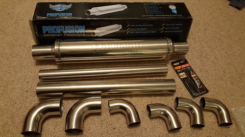 Any tips for welding stainless? Not done it before. Got a fairly basic hobby mig, so will be using disposable bottle gas. I think I need 309 grade wire (might be 308, need to check).
|
|
|
|
|
rowlesy
Vanorak
murdered the murderwagen Joined: 09 Oct 05 Location: up unit! Status: Offline Points: 6466 |
Post Options
Thanks(0)
Quote Reply
Posted: 08 Dec 16 at 17:31 |
|
Just the wire will do chap and slow your wire speed down to get the heat in - don't be tempted to cool anything down quickly to get the job done you'll get cracks either sides of the welds
|
|
|
UberFukz broke another! sucky sucky five dollah!
always out numbered never out gunned! RWS welding 07846 380 467 (worcs) |
|
|
|
|
Forden341
Not Quite Newbie 
Joined: 27 Aug 14 Location: Dorset Status: Offline Points: 21 |
Post Options
Thanks(0)
Quote Reply
Posted: 08 Dec 16 at 19:13 |
|
I'd be interested in knowing what your plans are with the exhaust and seeing how it develops. I have an 16v ABF in my crewcab running a temporary exhaust set up using a JX silencer. It's been like that for 6yrs now!!
You bought the stainless flange from me so I'm just about to do something similar. All the best. Bert. |
|
|
|
|
rowlesy
Vanorak
murdered the murderwagen Joined: 09 Oct 05 Location: up unit! Status: Offline Points: 6466 |
Post Options
Thanks(0)
Quote Reply
Posted: 09 Dec 16 at 06:38 |
Can't rush perfection!
|
|
|
UberFukz broke another! sucky sucky five dollah!
always out numbered never out gunned! RWS welding 07846 380 467 (worcs) |
|
|
|
|
club joker 84
Groupie
Joined: 21 Jul 09 Location: Cornwall Status: Offline Points: 138 |
Post Options
Thanks(0)
Quote Reply
Posted: 21 Jan 17 at 22:53 |
|
Too right, no point in rushing! I have done a bit more though...
First stop was a speed sensor. I know that these are available from Brickwerks, RJES and Speedpuls in Germany, but I thought that i might be able to make one. Had a dig around on the net and found this website where a guy in America has made one using a Hall effect sensor, a zener diode and 2 resistors, probably less than £5. He is putting it in a Subaru conversion, and the ECU only wants a 5V signal from the speed sensor. I believe that the AGG ECU wants 12V. What I have done is to swap the 5V Zener diode for a 12V one. I am no expert, but I think that this will do the trick. I have tried to add in an LED just to make diagnostics a bit easier. I made the circuit from the website up on a small piece of prototyping board which I had filed to shape to fit in place in the speedo as per the factory sensor. Here's a few pics... Testing the circuit to see if it works. 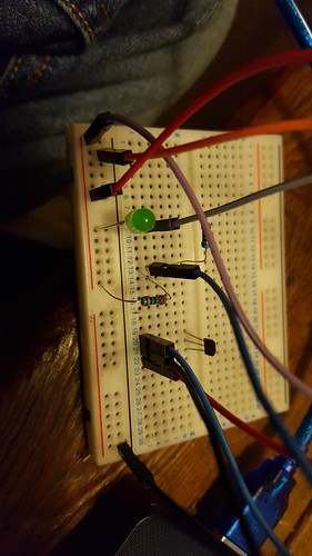 Circuit in place on rear of speedo. [ 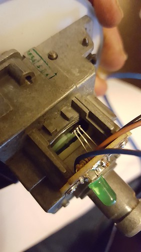 Note that hall sensor has to be bent to shape and located pretty close to the rear of the speedo to pick up the magnet that is already on it. 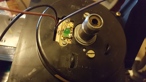 Here's a view of it all in place and bolted back together again. Not as neat as the professional ones, but a fair bit cheaper. Definitely gives a signal output when I have run the speedo with my drill. LED doesn't work, but I went for quite large resistors. As long as the signals works I am not too worried. Not tried connecting it all up to the van yet, but it seems to work on the bench. Time will tell...
|
|
|
|
|
club joker 84
Groupie
Joined: 21 Jul 09 Location: Cornwall Status: Offline Points: 138 |
Post Options
Thanks(0)
Quote Reply
Posted: 21 Jan 17 at 23:28 |
|
i have also made a start on the exhaust. I have a stock na diesel backbox, so really just need to connect this to the AGG exhaust manifold. I bought the following from Profusion Exhaust (all in 1.5mm wall thickness):
2 x 2.25" 57mm 90 degree Tight 1D Mandrel Exhaust Bend T304 Stainless Steel Polished 2 x 1.75" 45mm 90 degree Tight 1D Mandrel Exhaust Bend T304 Stainless Steel Polished 1 x 1.75 inch X 500mm 304 stainless steel exhaust pipe 1.5mm Wall Tube 1 x 2.25 inch 4 x 4 Round 18 inch Polished Stainless Steel Profusion Universal Exhaust Silencer 304 Stainless Steel Exhaust Lambda boss Nut Weld-on M18 x 1.5 O2 Oxygen sensor 2.25" inch 57mm Stainless Steel Joint Clamp heavy duty exhaust band Hi-Temp 1100°c Exhaust Assembly Paste Sealer Repair putty Hole Crack joint kit I did also have the stainless flange as well, but I made a complete balls of welding it and warped it. Doh! As well as the above, I got a reel of 309 stainless welding wire and a cylinder of gas. Because I warped the stainless flange I had, I went with the original flange and just hacksawed the old flexible mounts off it. The old exhaust just pulled off. This left two stubs approx1" long. The 1.75" tube was a good fit over these, so I just slipped it over and welded it in place. I just kept chopping and cutting and trying it in place and tacking it together. I tried to tried to keep the primary pipes reasonably long, as I understand this gives better low down torque, they are probably a bit longer than stock. The 16" silencer is a pretty tight fit. I cut down the flanges on the end to shorten it. It just about fits, but a 14" would probably be better. The only other significant change was that I cut the flange off the original van exhaust. This means that the new exhaust can just clamp over it. Pictures tell the story really. Hoping to finish this off tomorrow, as it is only tacked in place at the moment. 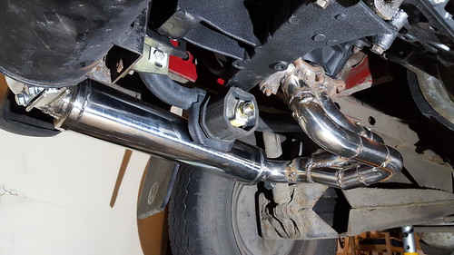 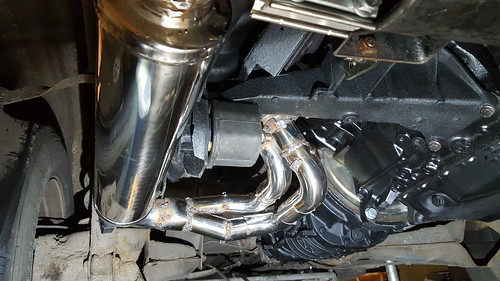 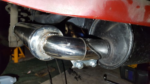 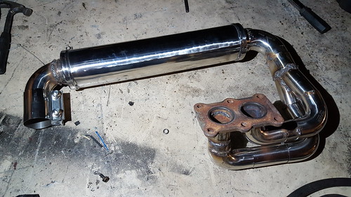 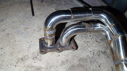 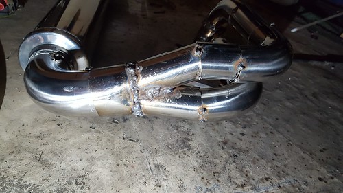 Impressed so far with the quality of the parts from Profusion. Nice and thick and really well made.
|
|
|
|
|
fufflenarnia
Vanorak
#1 Cable Shift Bitch Joined: 04 Sep 10 Location: Redhill, Surrey Status: Offline Points: 1362 |
Post Options
Thanks(0)
Quote Reply
Posted: 21 Jan 17 at 23:32 |
|
Good work
|
|
|
|
|
club joker 84
Groupie
Joined: 21 Jul 09 Location: Cornwall Status: Offline Points: 138 |
Post Options
Thanks(0)
Quote Reply
Posted: 22 Jan 17 at 22:35 |
|
Thanks mate - feels like I am making progress!
Finished the exhaust off today. Welded it all up and fitted it all up. Nice and quiet now  . Doesn't seem to leak anywhere. I also dropped the standard exhaust down a bit because it barely had any clearance from the rear valance. Here are a few pictures: . Doesn't seem to leak anywhere. I also dropped the standard exhaust down a bit because it barely had any clearance from the rear valance. Here are a few pictures:All welded up - 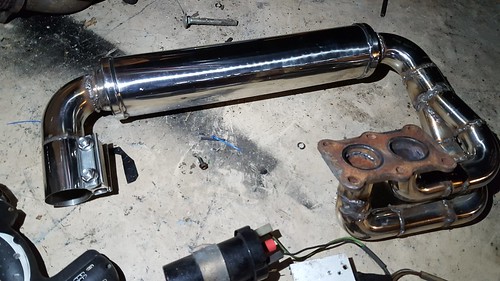 Fitted - 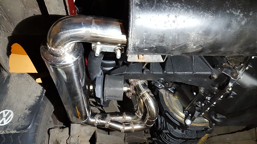 Pretty happy overall. Job left to do: - refit clocks and connect speed sensor - fit fuel pump and filter mounts - T eberspacher (sp?) into fuel return line - tidy up fuel pipes in engine bay - fit gear linkage - fit new CV joints (old ones are knackered!) - put front seats back in - MOT - take kids camping in newly working van - fit sub under passenger seat (non essential!) - got an idea to put together and MPGuino. (again, non essential!) Immobiliser seems to be quite choosy. Golf key needs to be taped right over the key reader coil before it will start, Bit annoying, because I have cut away part of the steering column so that it fits around the ignition barrel, but it won't work in this position.
 Would like to have it so that i can combine my van key with the golf key. Any ideas anyone? Do the coil readers tend to become less sensitive over time? Would like to have it so that i can combine my van key with the golf key. Any ideas anyone? Do the coil readers tend to become less sensitive over time? |
|
|
|
|
Post Reply
|
Page 123 4> |
| Tweet |
| Forum Jump | Forum Permissions You cannot post new topics in this forum You cannot reply to topics in this forum You cannot delete your posts in this forum You cannot edit your posts in this forum You cannot create polls in this forum You cannot vote in polls in this forum |


 Topic Options
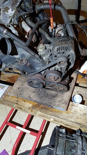
 Lots of bubbles in coolant tank though, so
possible head gasket?
Lots of bubbles in coolant tank though, so
possible head gasket? 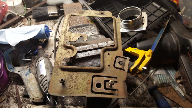
 club joker 84 wrote: